


AN EQUALIZER
Page 90
If you've noticed an error in this article please click here to report it so we can fix it.
for Four-wheel Brakes
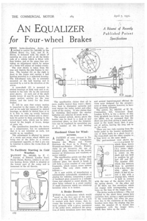
THE brake-equalizing device described in patent No. 343,489, by the Gilford Motor Co., Ltd., and E. B. Horne, is designed with the object of ensuring an even pull on all the brake rods of a vehicle which is fitted with four brakes, and at the same time providing an adjustment which by means of a worm will adjust all brakes evenly.
The view shown is taken from the rear and depicts the side frames in section. The bracket (8) on the right is fixed to the frame and carries a ball bearing mounted in a spherical housing. The bell-shaped tube (9) is rotatably mounted on the ball bearing and is operated by a rod in the direction of the arrow.
A cross-shaft (1) is mounted in slotted bearings at both ends and is attached to the tube (9) by the universal joint shown. At each end of the shaft double levers (5 and 6) are keyed, the upper portion serving for the rear brakes, and the lower for the front brakes.
It will be seen that rotary motion is imparted to the centre of the shaft, and as its ends'ate 'mounted in slotted bearings, as shown in dotted lines at 4; it is free to take up evenly between ' the front and rear brakes-and to distribute its power to them according to the prearranged ratio, which can be determined by the length of levers, design of cams, etc.
The specification describes the device as a compensator, but we understand that it is not intended as such, but merely as an equalizer.
The adjustment is effected by means of a worm and worm wheel which can bring two of the holes in a vernier arrangement opposite, so that a pin can J e inserted to relieve the worm from all strain.
To Facilitate Starting in Cold ' Weather.
PATENT No. 343,029, by F. C. Jearum, of Eldoret, London Road, North Cheam, Surrey, relates to an electric heating device which is situated at the lowest part of the sump and is immersed in the oil therein. The specification claims that oil is • more readily heated than water ; therefore, heat is dissipated upwards and soon warms the water jacket and other parts of the engine, It also claims that bywarming the' engine the starter batteries are relieved of much work.
The control switch, shown above the heater, can be fixed to a dash or any convenient• place, so that the temperature canbe regulated by energizing one or a number of the four heating members.
Hardened Glass for Windscreens.
A PATENT of some interest is No.
310,838, in which Conmagnies Reunies des elaces and Verras Speciaux du Nord de la France, of Bonssois-sur-Sambre (Nord), France, claim as an invention the use of tempered glass, obtained in the known manner as windscreens and windowS of motor vehicles The specification points out that such glass will resist shocks better than ordinary glass, but should it break it will form a great number of very small fragments, which cannot cause serious wounds. The only claim reads as follows :— As a new article of manufacture a substantially unbreakable windshield or glazing for vehicles, comprising a panel of hardened glass mounted in a suitable frame and adapted to resist shocks, the glass being reduced to a great number of small fragments which are relatively harmless when it is broken.
A Brake Booster.
IDEAS for mechanisms which would speed up the first part of the movement of a brake until the shoes are well in contact with their drums, then increase the leverage in order to obtain more pressure with a given movement of the pedal lever,, attracted the attention of many inventors some time back, and several ingenious% and efficient devices were designed for the mulles° ; none of these appears, however, to have been generally adopted. The patent, No. 343,717, of W. W. Constantine, 111, Grosvenor Road, London, 8.W.1, is for a device of this kind, in which two levers, one long and one short, are so arranged that the short one acts first, giving a rapid movement to the brake shoes, then it goes out of action, leaving the long one to do the work.
There are two rods running from the brake pedal to the booster mechanism; one of them leads to a short lever on the cross-shaft and the other couples to a long lever on the same shaft. The part-sectional view shows the
,arrangement by which these levers alternately operate t h e cross shaft. Both levers are free to rotate on the shaft and are held in position by collars (27 and 37). The member (53) which lies between them is provided with a key, but can slide along the shaft ; it has at one end a dog with a sloping face, which is held in contact with the case of the shorter lever hY the spring shown. At the ,other end of 53 there are fine serrations which can engage with corresponding serrations on the boss of the longer lever.
The device works as follows :—The rod co\upled to the short lever comes into operation first, giving a rapid movement to the cross-shaft, but when the pressure due to the resistance of the brgke becomes more than the sloping dog can resist, the member 53 is forced ' into engagement with the longer lever, which then takes up the work.