


Patents Completed.
Page 22
If you've noticed an error in this article please click here to report it so we can fix it.
Complete specifications of the following patents will be sent to any address in the United Kingdom upon receipt of eightpence per copy at the Sale Branch, Patent Office, Holborn, W.C.
STEAM TRACTOR. —.Allan.— No. 5,108, dated 2nd March, 1909.—This invention relates to traction engines and tractors and has for its abject to enable long distances to be travelled without replenishing the supplies in the feedwater tanks, and also to prevent the
escape of visible exhaust steam to atmosphere. A condenser is arranged immediately beneath the awning of the tractor ; this condenser is provided with alternating steam and air passages or channels. The steam from the exhaust is led to the front end of the condenser, and flows, through the steam channels therein, to a header at the opposite end ; the latter end is connected, by means of suitable piping. to the feed-water tanks. The air channels of the condenser are connected at that end nearest the driver, by means of a header and suitable piping, to a centrifugal fan which forces alr through the condenser to the front end of the latter, and from thence to the ash pit. Thus the warm air from the condenser is utilized to assist combustion. A superheater is also provided and this is disposed in the MO:1TP box.
Bopy-Tr I.TING MECHANISM. — Deighton's Patent Flue and Tube Co.— No, 7,095, dated 24th March, 1909.—This invention relates to improved means for tilting the body of a commercial-motor vehicle. The body is carried en an under flame, and is supported, at its front end, hy rollers carried by the body and running on the side members of the underframe, and at the rear end, by rollers which are carried by the under-frame, arid these latter rollers form a hinge whereby the body may be tilted to discharge its load. For this purpose the body has mid-way of its length two curved brackets which, when the body is moved backwards, engage the rollers on the under-frame and prevent further movement of the body in that direction. Mounted longitudinally of the vehicle is a screw shaft which is driven, through suitable bevel wheels and reducing gear, by the motor. On the screw shaft. is a nut that is connected by two links to the body, so that, when the screw shaft is rotated, the body will be moved either backwards or forwards according to the direction of rotation. In order to tilt the body before it has reached the limit of its backward movement, cam brackets are provided on the side members of the under-frame. A pedal and clutch are provided for the purpose of operating the screw shaft. The tilting operation is as follows :—The screw shaft is rotated by applying the pedal ; this movement causes the body to be forced backwards, and the rollers carried by the body ride up the cam brackets so that the body is first slightly inclined. Upon further movement in the backward direction, the curved brackets engage the rear rollers; further movement in a backward direction is thus prevented. The body finally turns about the rear rollers into the position shown in dotted lines. When it is required to re-turn the body on to the frame it is only necessary to rotate the shaft in the reverse direction.
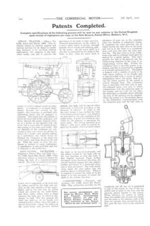
CARBURETTERS. — Pearmain and Another.—No. 5,406, dated 5th March, I909.—This carburetter provides fur the
admission of pure air to the cylinders when the throttle is completely closed. It comprises two main portions, one of which carries the fuel valve at its lower end and is in the form of a cylindrical liner, and over this liner the other portion fits. The fuel valve is of the mushroom type and is yieldingly held upon its seating by a spiral spring. This valve permits ths fuel to be sprayed into the carburetting chamber in the form of an outspreading conical film. Within the cylindrical liner a movable piston is arranged, and this is connected by a spindle to a suitable operating lever. The piston is formed with a number of ports in its wall—about midway of its length—and is also provided with a recess or groove immediately below the ports, thus giving the lower portion of the piston a conical internal form. The cylindrical liner is provided with four sets of radially-disposed ports, two sets of which communicate with the induction pipe of the engine, and two with the air inlet ; the latter have a rotatable sleeve whereby the area of the opening can be adjusted. When the piston is in the position shown in the illustration communication with the induction pipe and the fuel valve is
completely cut off, but air is permitted to pass to the engine by way of the two middle sets of ports in the liner and the external groove formed in the piston. When, however, the piston is raised, these two middle sets of ports are closed, and the ports at the extreme ends of the liner are opened. thus permitting air to flow past the fuel valve to the induction