 1
1 2
2 3
3 4
4 5
5 6
6 7
7 8
8 9
9 10
10 11
11 12
12 13
13 14
14 15
15 16
16 17
17 18
18 19
19 20
20 21
21 22
22 23
23 24
24 25
25 26
26 27
27 28
28 29
29 30
30 31
31 32
32 33
33 34
34 35
35 36
36 37
37 38
38 39
39 40
40 41
41 42
42 43
43 44
44 45
45 46
46 47
47 48
48 49
49 50
50 51
51 52
52 53
53 54
54 55
55 56
56 57
57 58
58 59
59 60
60 61
61 62
62 63
63 64
64 65
65 66
66 67
67 68
68 69
69 70
70 71
71 72
72 73
73 74
74 75
75 76
76 77
77 78
78 79
79 80
80 81
81 82
82 83
83 84
84 85
85 86
86 87
87 88
88 89
89 90
90 91
91 92
92 93
93 94
94 95
95 96
96 97
97 98
98 99
99 100
100 101
101 102
102 103
103 104
104 105
105 106
106 107
107 108
108 109
109 110
110 111
111 112
112 113
113 114
114 115
115 116
116 117
117 118
118 119
119 120
120 121
121 122
122 123
123 124
124 125
125 126
126 127
127 128
128 129
129 130
130 131
131 132
132 133
133 134
134 135
135 136
136 137
137 138
138 Scammell Routeman goes double-drive
Page 76
Page 77
If you've noticed an error in this article please click here to report it so we can fix it.
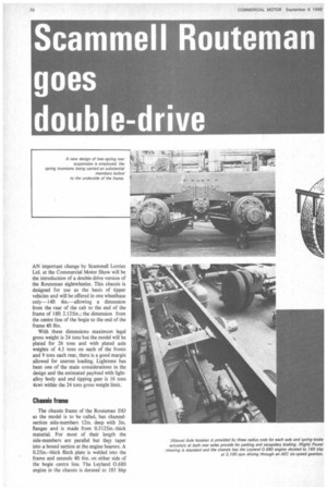
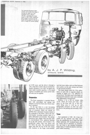
AN important change by Seammell Lorries Ltd. at the Commercial Motor Show will be the introduction of a double-drive version of the Routeman eightwheeler. This chassis is designed for use as the basis of tipper vehicles and will be offered in one wheelbase only-1 4ft 4in.—allowing a dimension from the rear of the cab to the end of the frame of 18ft 2.125in.; the dimension from the centre line of the bogie to the end of the frame 4ft 8in.
With these dimensions maximum legal gross weight is 24 tons but the model will be plated for 26 tons and with plated axle weights of 4.5 tons on each of the fronts and 9 tons each rear, there is a good margin allowed for uneven loading. Lightness has been one of the main considerations in the design and the estimated payload with lightalloy body and end tipping gear is 16 tons 4cwt within the 24 tons gross weight limit.
Chassis frame
The chassis frame of the Routeman DD as the model is to be called, has channelsection side-members 121n. deep with 3iit flanges and is made from 0.3125in.-thick material. For most of their length the side-members are parallel but they taper into a boxed section at the engine bearers. A 0.25in.—thick flitch plate is welded into the frame and extends 4ft 6in. on either side of the bogie centre line. The Leyland 0.680 engine in the chassis is derated to 185 bhp at 2,100 r.p.m. and the drive is through a 17in. strap-drive clutch with air-assisted hydraulic actuation to an AEC six-speed constant mesh overdrive gearbox. A five-speed version is available and various power takeoff units can be supplied.
Suspension
The front suspension is standard Routeman with semi-elliptic leaf springs and dampers on the first front axle. Power-steering is standard.
At the rear there is a new two-spring suspension. The springs are mounted on the tops of trunnions which are carried on spindles from substantial brackets bolted to the underside of the frame. Above the trunnion-bracket mounting position there is a heavy fabricated cross-member. The springs themselves have slipper ends and they bear on case-hardened 0.5in. spherical bearings set in the axle casings. Axle location is by parallel-link radius rods—one above and two below the axles. The centrally-located upper units link the top of the axle casing with brackets in the bogie cross-member and the lower radius rods are fitted between pivot points on the axle casings and below on the trunnion brackets.
The bogie design caters for 3.5in. articulation on each side so opposite wheels are capable of taking up a 7in. difference in ground level. The axles used in the bogie are Leyland hub-reduction types and a lockable third differential is incorporated.
Braking is by a full air system with 15.5in. drums all round and 4.5in. wide shoes at the front and 7in. at the rear. Total lining area is 1,143 sq. in. and spring-brake actuators at both rear axles provide for the parking and secondary functions.
Tyres
Tyre equipment is 9.00-20, I2-ply but 10.00-20 are optional and other items from the specification are a 36ga1 fuel tank (40gal optional). 24V insulated-return electric circuit and an alternator as standard. The cab fitted is the standard Routeman design being of reinforced plastics with fourpoint rubber mounting.