


BUILDING AMBULANCES FOR OVERSEAS.
Page 49
Page 50
Page 51
Page 52
Page 53
If you've noticed an error in this article please click here to report it so we can fix it.
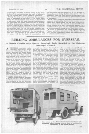
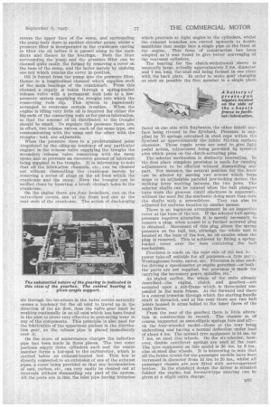
A Morris Chassis with Special Bonallack Body Supplied to the Colombo Municipal Council.
ASTURDILY constructed ambulance body mounted on a MorrisCommercial Colonial-type chassis has recently been built by Messrs. Bonallack And Sons, at their Cable Street works, London, El. This vehicle is being supplied to the Municipal Council of Colombo, and, it is stated, is to be employed in carrying native liatients.
The general build of the ambulance is strong and simple. The body is of the box type, having single-piece side panels, which give it a clean appearance, and wide doors at the rear, which, as can be seen from the accompanying illustration, fold right back against the sides of the vehicle. Two frosted glass lights are provided on each side of the body. A drop window, which is operated by a winder of itandard pattern, is fitted into each rear door and is equipped with a spring blind.
Owing to the fact that the ambulance is to be used in a very hot climate, ventilation has received extra attention. The top halves of the side lights are made to open and louvres are provided over each rear window, the draught of air induced through the latter being so strong that special cloth shutters have been fitted over them on the inside. A neat ventilator, which can be opened or closed by hand, is built into theroof.
The St. John Ambulance pattern stretchers are carried at the near side of the vehicle, the lower stretcher being equipped with an adjustable, cushioned head-rest. The upper stretcher-carrier is of standard pattern, whilst the lower one is of somewhat unusual construction, being designed so that the runners can be made to slide out of the body for almost half their length. This enables the stretcher to be placed in position or taken from the ambulance with o minimum of trouble, as the bearer at the patient's head is able to mount straight into the body between the runners. This ease of operation isfurther facilitated by a strong, folding double-step at the rear.
The ambulance is equipped with a long, comfortable seat for .the convenience of the attendants, and beneath it is ample locker:space for medical and other essentials. A special type of lamp is used for interior lighting.
The driver's compartment is roomy, having seating accommodation for two persons beside the driver. A space for tools is provided beneath the cushioned front seat. Two mall, . rectangular lights are built into the panels, one on each side of the compartment. Side curtains are provided so that the cab can be totally enclosed. There is a sliding window in the bulkhead separating the driver's compartment and the interior.
The body is tastefully finished in cream with gold-leaf and red lettering.
The special features of the chassis include an extra large top radiator-tank, whilst the cooling block is of the film type instead of the usual MorrisCommercial gilled-tube pattern. An air filter is fitted to the carburetter to protect the engine from the evil effects of dust. Special ambulance springs and Smith shock-absorbers are fitted all round. The gear ratio of the rear axle is 8.3 to 1, which, combined with the fact that the chassis iS equipped with Dunlop low-pressure tyres of 33-in. by 5-in. dimensions, should give the vehicle a good turn of speed.
THE COMMERCIAL' MOTOR 74 THE experience in both passenger and goods vehicles possessed by Guy Motors, Ltd., of Fallings Park,
Wolverhampton, must always be taken into account when it brings out a new chassis. Indeed, certain sections of the commercial vehicle world consider Guy developments as typical and indicative of the trend of the industry. The latest products of this go-ahead concern—two new 6-cylindered chassis—have been introduced in response to a definite demand for satisfactory large coach or bus chassis. Ease of maintenance has been considered from the points of view of both engine and chassis, a feature which, coupled with a general robust construction—typical of all Guy products— should make an appeal to the heavy-vehicle user.
Before describing the new chassis in detail it would seem opportune to give a brief outline of the sizes of the vehicles. Actually, the general layout for the new chassis is on lines almost identical with those that have preceded them, the main difference lying in the design of the engine, clutch and gearbox. The fourwheeled chassis can be obtained in two sizes of wheelbase-16 ft. 5 ins. and 19 ft. 11 in.—whilst the sixwheeled chassis can be secured in three alternative sizes-46 ft. 7 ins., 18 ft. 6 ins., and 19 ft. 11 in., the latter chassis being suitable for 60-seater, 70-seater and 74-seater double-decki buses respectively. On the largest chassis, a single-deck saloon bus seating 39 passengers can be supplied, conforming with the' Ministry of Transport regulations restricting the overall length to 30 ft.
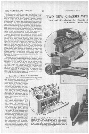
Turning now to a consideration of the power unit. The four-wheeled chassis has a slightly smaller engine than the six-wheeled type. The smaller engine has six cylinders with a bore of 4 ins, and a piston stroke of 51 ins. It develops 45 b.h.p. at 1,000 r.p.m., 75 b.h.p. at 2,250 r.p.m., and reaches its maximum of 80 b.h.p. at 2,300 r.p.m. The larger engine has a cylinder bore of 41 ins, and a piston stroke of 51 ins. This engine develops 56 b.h.p. at 1,000 r.p.m., 96 b.h.p. at 2,200 r.p.m. and 100 b.h.p. at 2,300 r.p.m. It will be seen, then, that a high terque figure is obtained at a comparatively low speed• of revolution.
Durability and Ease of Maintenance.
The keynote to the whole construction of the power unit is durability with ease of maintenance. Thus, we find that all bearing surfaces are exceptionally large and well lubricated, whilst, in addition, care has been taken that excessive lubricant does not pass into the combustion chambers, and so cause oiling up when the engine is running light or idling. Broadly speaking, there are three main components in the engine, the cylinder blocks, crankcase and the sump. We will deal first with the crankcase.
This is an aluminium casting, stiffly ribbed and supported in a sub-frame at four points. The sub frame is specially arranged to avoid frame distortion being passed on to the engine, and will be dealt with later. All the seven bearings for the crankshaft are formed in webs running right across the crankcase casting. The camshaft, located high up within the crankcase, is supported on no fewer than eight bearings, which, like those for the crankshaft, are all firmly held. The main crankshaft bearings, as well as the bigend bearings for the connecting rods, are housed in bronze cages, the latter having laminated -shims, so that wear can be taken up very
n32 quickly and easily. The connecting rods, incidentally, are of Duralurain, bushed at the small end with phosPhor bronze in order that excessive wear at this point may be cut out The gudgeon pins are fixed on to the pistons. The camshaft bearings are of phosphor bronze.
At the forward end of the crankcase the distribution gear is housed. The whole of the drive for the camshaft, dynamo, water pump and magneto is obtained by skew spur gears, the mesh for all the pinions, except the magneto and water-pump pinion, being adjustable for mesh. A spur pinion on the end of the crankshaft meshes with an idler wheel, which in turn drives' the camshaft, a drive being taken from this latter wheel to another idler which forms the driving medium for the dynamo. The two idlers are mounted by a three-stud flange attachment, the holes in the flanges being 1-16th in. greater in diameter than the diameter of the studs ; thus, when the crankshaft main journals have become worn and the bearings have been taken up, the gears can be reme.shed to suit the new pinion centres,iwhilst in addition wear in the teeth can be compensated by closer engagement.
On the top of the timing case a shaft is run at right angles to the centre line of the crankshaft; the extremities of the cross-shaft providing the drive for the magneto on the off side and the water pump on the near side. There is a spiral gear on the centre of this shaft which meshes with the top of the camshaft pinion. The drive for the magneto is taken through a Simms vernier coupling which, by virtue of its generally accessible Position, enables the engine to be retimed very easily without disturbing any component other than the instrument itself.
The Mounting of the Water Pump.
The water pump is ingeniously arranged in that a carrier bracket is bolted up to the crankcase and a special fitting used for attaching the pump to the bracket. A groove and tongue joint provide the drive to the vane spindle, and merely by slacking off one pin on the bracket the whole pump can be withdrawn for inspection or repacking. The gland is, of course, internal, and the packing is spring loaded into contact with the gland. There is another interesting feature concerning the Water pump in that end thrust has been entirely ayoided by fitting a doublevane rotor in which the reactions balance each other. This has been found to be a valuable asset if Ion gevity of the life of the pump parts be desirable. On each side of the exterior of the crankcases trays are formed between the supporting arms, which makes the appearance of this unit very neat, as well as providing adequate protection for the engine from any mud and water that may be thrown up by the road wheels.
Provision is made for the accommoda.tion of a starter in the cradle, formed in a junction of the side of the crankcase and the tray. The dynamo is also housed in a Cradle and is driven by an internaltoothed coupling from a spindle projecting from the reAr cheek of the timing cover. This spindle is carried on a substantial plain bearing and is located by an addi tional ball bearing, which takes its support from the forward end of the gear.
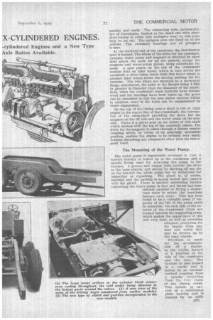
Before describing the lubrication system we will deal with the cylinders and valve gear. The cylinders are formed in two castings of three bores each, which are firmly bolted to the crankcase by a number of substantial studs. There are many interesting features concerning the construction of these components, the most important of which is undoubtedly the arrangetnent that has been made to maintain' an even water temperature around the cylinder. To this end the inlet water pipe is run along the side of the cylinders remote from the valves, each block of cylinders having an aluminium plate covering a rectangular aperture in the water jacket. The water inlet pipe is cast integral with the covers, and communicating therewith are four cast-in pipes, the ends of which project between the cylinders and approach very closely the valve ports. In this way cool water is directed right on to the hottest part of the engine, leaving a small-diameter leak hole in the water supply pipe cover plate to take care of the side of the cylinder block remote from the valves.
Another feature is that the heat from the exhaust pipe is taken as far as possible away from the cylinder bores and valves by water-jacketing the exhaust pipe for some 21 ins. This also serves the purpose of making the volume of the water space around the valves amply large enough to ensure even temperatures, whilst the mixture entering through the inlet ports, also waterjacketed, is warmed sufficiently to ensure efficient vaporization.
The well-known Guy type valve gear is included in the layout. Our readers will recall that the valves are inclined to the centre line of the cylinders, an arrangement which allows the valves to be operated by a camshaft located in the crankcase and, with a sloping cylinder head, gives a very good form of combustion chamber, consequently a comparatively high compression * pressure can be used, with corresponding gains in power and economy without incurring the bugbear of detonation.
. The rocker gear is a particularly sturdy job. There are two separate shafts used, each of which is contained in an aluminium casting attached to a face on the crankcase, a support being arranged for the shaft between each rocker. There is now no offset to the line of the two arms of the rocker (one to the cam and the other to the valve), a feature that enables a lighter, yet stronger construction to be
B34 obtained. The shaft is of hardened steel and all bearings are bronze bushed. The lubrication of the valve gear will be dealt with under the general lubrication of the engine.
Returning now to a consideration of the cylinders and cylinder heads. The latter are perfectly fiat castings, water-cooled throughout the 'whole of their surfaces. Each head (covering three cylinders) is attached to the cylinder face by no fewerthan 17 well-placed, substantial studs, the gasket between the two being called upon to seal the compression pressures only. The water connections are made tight by a series of double conical rubber rings, which fit into chamfered recesses in the upper faces of the cylinder blocks and the lower faces of the heads. The sparkingplug holes are, of course, located as near as possible, to the centre of the combustion chamber and, by virtue of the plain nature of the exterior of the heads, they are very accessible when cleaning or replacement becomes necessary. Castiron four-ring pistons are used.
We will now turn our attention .to the lubrication system. The most noticeable feature regarding the sump is the fact that it is extremely well ribbed, to ensure adequate cooling for the oil contained within it. The usual Guy system of pressure feed to the main bearings is used, together with a low-pressure system for supplying troughs into which-the big-ends of the connecting rods may dip. Special care has been taken in the layout for the sump to ensure that the lubricant is clean before it enters the bearings. To this end there is a large coarse-mesh gauze which covers the upper •face of the sump, and surrounding the pump body there is another circular gauze, whilst a pressure filter is incorporated in the crankcase casting to filter the oil before it is passed along to the main ducts and thence to the bearings. Both the filter surrounding the pumpand the pressure filter can be cleaned quite easily, the former by removing a cover on the base of the sump, and the latter merely by undoing one nut which retains the cover in position.
Oil is forced from the pump into the pressure filter, thence to a longitudinal channel which supplies each of the main bearings of the crankshaft. From this channel a supply is taken through a spring-loaded release valve with a permanent leak hole to a lowpressure system supplying the troughs into which the connecting rods dip. This system is ingeniously arranged to overcome certain troubles. When the engine is idling very little oil is required for either the big-ends of the connecting rods or for piston lubrication, so that the amount of oil distributed to the troughs should be small. To regulate this pressure there are, in effect, two release valves, each of the same type, one communicating with the sump and the other with the troughs; both are adjustable. .
When the pressure rises to a predetermined point (regulated by the oiling-up tendency of any particular engine) in the release valve supplying the troughs the secondary release valve connecting with the Sump opens and • so prevents an excessive amount of lubricant being supplied to the troughs. It is interesting to note that all the lubrication channels, etc., can be cleaned out without dismantling the crankcase merely by removing a series of plugs on the oil lines within the crankcase and the sump; Even the troughs can be swilled clean by inserting a brush through toles in the crankcase.
On the engine there are four breathers, two on the valve-chest covers, one at the front and cafe at the rear ends of the crankcase,. The action of discharging air through the breathers in the valve cover S naturally causes a tendency for the oil mist to travel up in the direction of the air flow, thus the valve gear must be working continually in an oil mist which has been found in the past to prove very effective in preventing wear in any of the components. This principle is also used for the lubrication of the uppermost pillions in the diStribution gear, as the release pipe is placed immediately over it.
On the score of maintenance charges the induction pipe has been made in three pieces. The two outer portions supply three cylinders each and the centre member forms a hot-spot to the carburetter, which is carried below an exhaust-heated box. This box is directly connected to an extension of one of the exhaust pipes, a cover being provided so that any accumulation or soot, carbon, etc:, can very easily be cleaned out at intervals without dismantling any part of the system.All the ports are in line, the inlet pipe having branches
which protrude at right angles to the cylinders, whilst the exhaust branches are curved upwards to double manifolds that merge into a single pipe at the front of the engine. This form of construction . has been : adopted as it was found to give better scavenging of the rearmost cylinders.
The bearing for the clutch-withdrawal sleeve is unusually large, actually approximately 3 ins, diameter and 7 ins, long, the stud end being formed in one piece with the back plate. In order to make gear changing as easy as possible the free member is a single plate faced on one side with Raybestos, the other fabrie surface being riveted to the flywheel, Pressure is supplied by 15 springs contained in steel cups within the flywheel at approximately the fabric friction surface diameter. Three toggle arms are used to give light pedal action, adjustment being provided by screwed pins which press on the clutch-actuating pins.
The selector mechanism is distinctly interesting. In the first place complete provision is made for running adjustments to be effected without dismantling any part. For instance, the neutral position for the lever can be altered by moving two .screws which form stops to an adjustable parallel jaw-locking device, tile striking lever working between the two Jaws. The selector shafts can be rotated when the ball plungers have worn the 'grooves (until slackness is apparent), without the need for the mechanic doing more than turn the shafts with a screwdriver. They can also be adjusted for endwise location by similar means.
There is an ingenious arrangement in an inspectioA cover at the base of the box. If the selector-ball spring pressure requires alteration it is merely necessary to remove a plug, when access to a further screwed plug is obtained. Movement of this plug alters the spring pressure on the ball, but, although the whole unit is located at the base of the box, no oil exudes when the plug is removed. This is achieved by fitting a springloaded _ cover over the boss containing the ball mechanism.
Provision is made on the nr side of the box fc7 power take-off suitable for all purposes—a tyre pin7:. Westinghouse brake, motor, etc. Provision is also made for driving a speedometer,or engine governor—or both ; the parts are not supplied, but provision is made for carrying the necessary gears, spindles, etc.'
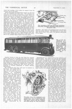
As stated earlier, the whole of the units already described—the engine, Clutch and gearbox—are mounted upon a sub-frame which is three-point suspended in the main frame. At the forward end there is a central trunnion through which the starting-handle shaft is threaded, and at the rear there are two ball joints housed in arms bolted to the inner faces of the main frame. • From the rear of the gearbox there is little alteration in construction to record. . The chassis is, of course, Supported on semi-elliptic springs fore and aft— oh the four-wheeled model—those at the rear being underslung and having a normal deflection under load of about 4 ins. The normal tyre equipment is 34 ins. by 7 ins. on steel disc wheels. On the six-wheeler, however, double cantilever springs are used at the rear. The tyre equipment on this model is 36 ins, by also on-steel disc wheels. It is interesting to note that all the brake drums for the passenger models have been _ increased in diameter from 16 ins. to 20 ins., whilst all passenger chassis are now fitted with servo-operated brakes. In the standard design the driver is situated liehind the engine, but forward-type steering can be given at a slight extra charge.