


A NEW British-made Details of the new BritishCLUTCF-I
Page 43
If you've noticed an error in this article please click here to report it so we can fix it.
made Borg and Beck clutch
AT the new works of the Borg and Beck Co., Ltd., at Clemens Street, Leamington Spa, Warwickshire, which is th be employed for the manufacture of clutches for motor vehicles, designs have been laid out for the production of a straightforward single-plate clutch suitable for commercial vehicles of up to about five tons pay-load capacity. The clutch is intended for chassis in which the gearbox is separate from the engine, and in producing it the company's object is evidently one of being prepared for any possible extension in the use of separate gearboxes. The London office of the company is at Brock Rouse, Langharn Street, W.1.
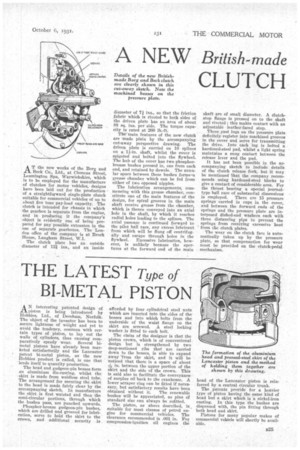
The clutch plate has an outside diameter of 12i ins., and an inside diameter of 7 ins., so that the friction fabric which is riveted to both sides of the driven plate has an area of about 88 sq. ins, per side. The torque capacity is rated at 260 lb.-ft.
Th'e' main features of the new clutch are -made plain by the accompanying cut-away perspective drawing. The driven plate is carried on 10 splines on a 14-in, shaft, whilst the cover is spigoted and bolted into the flywheel. The hub of the cover has two phosphorbronze bushes pressed in, one from each end, and retained by dowels. The annular space between these bushes forms4a grease chamber which can be fed from either of two opposed nipples.
The lubrication arrangements, commencing with this grease chamber, constitute one of the main features of the design, for spiral grooves in the main shaft receive grease from the chamber, which is thence conveyed into an axial hole in the shaft, by which it reaches radial holes leading to the splines. The axial passage is continued fomard to the pilot ball race, any excess lubricant from which will be flung off centrifugally and escape through holes in the flywheel. Excessive lubrication, however, is unlikely because the apertures at the forward end of the main
shaft are of small diameter. A clutchstop flange is pressed on to the shaft and riveted ; this makes contact with an adjustable leather-faced stop.
Three cast Jugs on the pressure plate definitely register into machined grooves in the cover and serve for transmitting the drive. Into each lug is bolted a hardened-steel pad, whilst a light spring maintains a snug contact between the release lever and the pad.
It has not been possible in the accompanying sketch to include details of the clutch release fork, but it may be mentioned that the company recommends using hardened-steel blocks to give a contact of considerable area. For the thrust bearing a special journaltype ball race of substantial dimensions is employed. There are 15 pressure springs carried in cups in the cover, and between the forward ends of the springs and the pressure plate are interposed dished-end washers each with three distancing pips to prevent the springs from receiving excessive heat from the clutch plates.
The wear on the clutch face is automatically taken up by the pressure plate, so that compensation for wear must be provided on the clutch-pedal mechanism.