


Simple Scheme for Unloading Containers
Page 60
If you've noticed an error in this article please click here to report it so we can fix it.
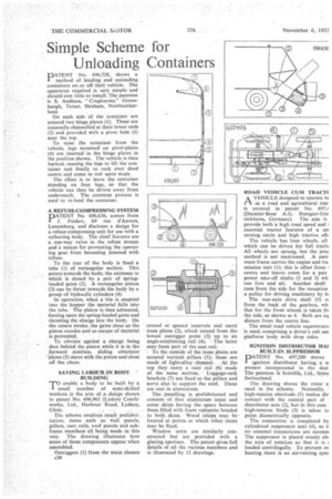
PATENT No. 696,728, shows a I method of loading and unloading• containers on ,or off their, vehicle. The apparatus required is very simple and should cost little to install. The patentee is S. Andison, "Cragknowe," Greenhaugh, Tarset, Hexham, Northumberland.
On each side of the container are secured two hinge plates (1). These are internally channelled at their lower ends (2) and provided with a pivot hole (3) near the top.
To raise the container from the vehicle, legs mounted on pivot-plates (4) are inserted in the hinge plates in the position shown. The vehicle is then backed, causing the legs to lift the container and finally to rock over dead centre and come to rest upon stops.
The effect is to leave the container standing on four legs, so that the vehicle can then be driven away from underneath. The converse process is used to re-load the container.
A REFUSE-COMPRESSING SYSTEM
PATENT No. 696,636, comes from Feidert, 69 rue d'Anvers, Luxemburg, and discloses a design for a refuse-compressing unit for use with a collecting body. The chief features are a one-way valve in the refuse stream and a means for preventing the operating gear from becoming jammed with refuse.
To the rear of the body is fixed a tube (1) of rectangular section. This points towards the body, the entrance to which is closed by a pair of springloaded gates (2). A rectangular piston (3) can be thrust towards the body by a group of hydraulic cylinders (4).
In operation, when a bin is emptied into the hopper the material falls into the tube. The piston is then advanced, forcing open the spring-loaded gates and thrusting the charge into the body. On the return stroke, the gates close as the piston recedesand so escape of material is prevented. .
• To obviate against a charge being . shot behind the piston while it is in the forward position, sliding obligator "plates (5) move with the piston and close off the chute.
SAVING LABOURIN BODY ' BUILDING
TO enable a body to be built by a small number of semi-skilled workers is the aim of, a design shown in patent No. 696,961 (Lydney Coach= Works, Ltd., Harbour. Road, Lydney. Glos).
The scheme employs much prefabrication, items such as wall panels, pillars, cant rails, roof panels and subframe menrihers all being made in this way, The drawing illustrates how some of these components appear when assembled.
Outriggers (l) 'from the main chassis A38
• extend at spaced intervals .and carry' • truss plates (2), .which extend from the lowest outrigger point (3) up to an angle-reinforcing rail: (4).. -The latter may form part of the seat rail. . • To the outside of the truss plates are secured vertical. pillars. (5); these are made of light-alloy channel.. At the top they carry a cant rail (6) made of. the same section.' • Luggage-reek' brackets (7) are fixed tO the 'pillars and serve also to support the roof. These are cast in aluminium.
.The, panelling is prefabricated and consists of thin all:minium. inner and outer skins having the space between them filled with foam vulcanite bonded to both skins. Wood inlays niay be located at points at which other items may be fixed.
Window units are similarly constructed but are provided with a glazing aperture. The patent gives full details of all the various members and is illustrated by 12 drawings. ROAD VEHICLE, CUM TRACT( A VEHICLE designed to operate b( t't as a road and agricultural trac is covered in patent No. 697,z (Daimler-Benz A.G. Stuttgart-Urn tiirkheim, Germany). The aim is provide both a high road speed and essential tractor features of a sm turning circle and high tractive elf(
The vehicle has four wheels, all which can be driven for full tracti■ All wheels are sprung, but the prec .method is not mentioned. A narr main frame carries the engine and Ira mission unit (I); this is offset from centre and leaves room for a pair power take-off shafts (2 and 3) wh run fore and aft. Another shaft runs from the side for the reception a pulley for driving machinery by bi
The rear-axle drive shaft (5) n from the back of the gearbox, wh that for the front wheels is taken ft.( the side, as shown at 6. Both are eq distant from the centre line.
The usual road vehicle superstrucu used,-comprising a driver's cab an platform body with drop sides, , .
IGNITION DISTRIBUTOR, ITV BUILT-IN SUPPRESSOR DATENT No. 697,200 shows I ignition distributor having a si pressor incorporated in the. desi, The patentee is Scintilla, Ltd., Soleu Switzerland.
The drawing shows the rotor a used in the scheme. Normally, • high-tension electrode (I) makes dir contact with the central part of . distributor arm (2), but in this case • high-tension blade (3) is taken to point diametrically opposite.
The connection is completed by cylindrical suppressor unit (4), so ti no external connections are necessa The suppressor is placed evenly abi the axis of rotation so that it is I loaded centrifugally. To prevent ov heating there is an air-venting syst(