


A COMBINED PETROL AND STEAM ENGINE.
Page 32
If you've noticed an error in this article please click here to report it so we can fix it.
A Résumé of Recently Published Patents.
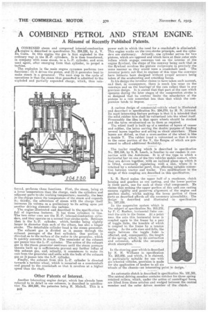
ACOMBINED steam and compound internal-combustion engine is described in specifiCation No. 204,230, by A. V. Da Costa. In this engine the gas is first, exploded in the ordinary way in the H.-P. cylinders. This-then transferred, in company with some steam, to a L.-P. cylinder, and even used again, after emerging from that cylinder, to propel a turbine.
The explosion in the main engine cynnders performs two functions :• (1) it drives the piston, and (2) it generates heat. to make steam in a generator. The next, step in the cycle of operations is that the steam thus generiKed is admitted to-the exploded and partially expanded charge, which, thus rein forced, performs three functions. First, the steam, being at a lower temperature than the charge, cools the cylinders and adjacent parts to the working temperature ; secondly, the heat in the charge raises the temperature of the steam and expands it; thirdly, the admixture of steam with the charge itself increases its volume as a preliminary to its acting upon yet 'another driving element—the turbine. The engine illustrated and described in the specification is full of ingenious features: It has three cylinders in line. The two outer cues are the H.-P. internal-combustion cylinders, and they operate on a. normal four-stroke cycle. Between then is the L.-P. cylinder, which, besides being slightly larger in diameter than each of the others, has also a. longer stroke. The detachable cylinder head is the steam generator.
The exhaust gas is divided as it passes through the exhaust passages of the first. cylinders. One portion is rfirected on to the surface of the water in the generator, which it quickly converts to steam. • The remainder of the exhaust gas passes into the L.-P. cylinder. The action of the exhaust gas in the steom generator continues until the steam pressure therein built up is sufficientete prevent any further influx of this exhaust gas, and, actually, it corninencee to make its exit from the generator and unite with the bulk of the exhaust gas as it passes into the. L.P. cylinder. Finally, the exhaust from this L.-P. cylinder is directed towards a turbine wheel, which is mounted on a. countershaft and geared to the crankshaft, so that it revolves at a.higher speed than the Phan.
Other Patents of Interest.
Another interesting engine design, which has already been referred to in detail in our columns, is described in specification No. 204,220, the patentee being H. Michell. This ia B48 power -unit in which the need for a. crankshaft is eliminated. This engine works on the two-stroke principle, and the cylin ders arestationary. Actually, one cylinder serves for two pistons, which are opposed and which have at their outer ends rollers which engage camways 'cut on the interior of the engine flywheel, the shape of the camway being such that as the flywheel revolves the pistons reciprocate in precisely the same manner as they would were a crankshaft used. The inventor 'points outthat in engines of this type the caraways hare hitherto been designed without proper account being taken of the accelerating and retarding forces.
In his design, the inventor claims tohave taken such account, and that, in: consequence, there is much less: wear on the camerays and on the bearings' of the cam rollers than in any previous design. It is stated that that part of the cam which operates during the later stages of the compression. stroke is so designed that its contour limits the retardation of the Pistons to a rate somewhat less than that which the conipreseion tends to impose.
A curious design of commercial-vehicle wheel is illustrated and described in specification No. 204,279, by H. N. Atwood. Its most interesting feature perhaps is that it is intended that the solid reibber tyre shall be-vulcanized into the wheel itself. Presumably the idea is that spare wheels should be stocked and the tyres revulcanized on to them as required.
The Wheel itself is built up of a number of layers of veneer and rubber, the latter serving the double purpose of binding several layers together find acting as shock absorbers. These layers are dished, so that a cross,section of the wheel is like a double Y. The rubber tread is vulcanized so that it rests in the outer portion of the Y, the flanges of which are -pre, sumed to afford additional flexibility.
The trailer coupling which is described in specification No. 204,154, by $., E. Leach, is familiar to our readers in connection with the Autohorse. It is of' the type -in which a horizontal bar en one of the two vehicles' Makes contact, when they are driven together, -with an inclined plane up which it is lifted, 'eventually registering with a Slot, where it is retained by a substantial pawl, thus effecting suitable connection between tractor and trailer. Two modifications in the design of this coupling are described in this specification.
L. R. Ravel makes the upper half of a crankcase, clutch housing and gearbox as one casting, and the lower portion in three parts, one for each of these vital component:S. He claims that making the upper portion. of this'urnt _one casting. ensures rigidity and preserves alignment, of the engine and gearbox shafts, :whilst making the lower_ portion of three parts as described affords all the necessary accessibility. The desi'=ed is described and illustrated in specification No. 197,938.
In the suspension system which is the subjeCt of specification No. 203,202, by P. C. Ruslion, horizontal links connect the axle to the frame. At a point near the axle this horizontal lever is coupled again to the frame by a pair of toggle links, the knuckle of which is coupled to the fra-me by a tension spring. A9 the axle rises and falls, the angle between the toggle links i affected, and, consequently, the length of the spring, which,' by its contraction and extension, affords the necessary shock absorption. '
In the steering gear which is described by E. ff. Williams in specification No. 203,850, and which, it is claimed, is particularly suitable for usewith six-wheeled vehicles, provision is made for the application of brakes to all six wheels of the chassis—an interesting point in design.
An automatic clutch is described in specification No. 181,381. The central driving-member contains notches for three spring retained rollers, which, under the action of centrifugal force are lifted from these notches and wedged between the central member and the outer driven member -of theclutch.