


Combined Mechanical and Cushion-type Universal
Page 36
If you've noticed an error in this article please click here to report it so we can fix it.
A UNIVERSAL joint for transtnis
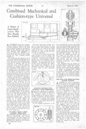
sion systems, designed to minimize torsional vibration, and at the same time to permit variation in the effective length of the propeller shaft together with relatively Wide angularity, is shown in patent No. 542,477 by T. Chariesworth and the Laycock Engineering Co., Ltd., Victoria Works, Sheffield, 8.
The underlying idea appears to be to combine the respective advantages of the mechanical and rubber-cushioned types, whilst eliminating their disadvantages. Angularity is afforded only by the mechanical joint, torsional impulses, variations in relative velocity, and axial movement being looked after by the cushion joint. No stresses caused by misalignment of the shafts are taken by the latter, and there is no sliding spline incorporated with the former to constitute a potential source of thrust loading on the transmission bearings.
Precise concentricity is maintained by the spigot, the rubber bushes being relieved of the function of locating the respective parts relatively to one another, as well as of the onus of • accommodating variations in the angle between the driven and driving shafts.
For the sake of clearness, the drawing shows part 4 in the same plane as part 6, although these parts are, in fact, angularly spaced by 99 degrees. On the driving shaft is mounted one fork (1) of the mechanical joint, the other fork (2) being carried by an 'intermediate member (4). The lastInamed can freely move axially and rotaxily on a central spigot (3) attached to the driven member (6). This intermediate member (4) carries the driving arms of the cushion joint which terminate in rubber bushes (7). The driv&i member (6) also carries similar arms and bushes, and the two sets are united by a pressed-steel floating outer casing (5).
AN EASILY BUILT LARGE TRAILER AMBULANCE
ATRAILER ambulance designed for easy manufacture and having accommodation for both sitting and lying patients, is shown in patent No. 542,087 by E. Matthews, 25, Chisholm Road, Richmond, Surrey.
The main framework consists of a pair of deep long members (4); these are set rather close together, leaving a well about 3 ft. wide for the whole length of the body. They rest upon cross-bars to which the axle and towbar (5) are 'attached.
At the level of the floor (3) the body space extends to the full width, and accommodates a pair of stretchers (2) at the rear. The front part (7) forms seating room for six patients, whilst a high-level seat (1) is intended for an attendant. A castor-wheel (6) can be lowered before detaching tile trailer, and enables the ambulance to be manoeuvred by hand. Jacks are fitted at both ends to give stationary stability.
I N patent No, 542,491 by H. McClean, E. Wortley and Crompton Parkinson, Ltd., Guiseley, Leeds, is shown a driving system for all electric vehicles. whether trolleybuses, battery-electrics, or engine-driven chassis with electric transmission. A feature of the scheme is that each road wheel is driven by its own electric motor.
In the simplest application of the idea, as illustrated, a motor (3) drives one road wheel through a suitable gear reduction housed in the casing (4), the novelty of the system lying, according to the claim, in the fact that the driving unit forms an integral part of the suspension system. As will be observed, the assembly is pivoted on the chassis at the point (2) and receives a helical spring (1) on a platform located over the axle. By removing, the need for a separate suspension framework, much weight can be saved.
The invention may be applied to steerable wheels by providing a suitable universal joint, whilst for narrow vehicles, such as small battery-electrics, the motors on opposite sides, instead of lying symmetrically, can be staggered and may overlap each other, to save space. An associated patent. No. 542,498, shows a system of torsionbar springing for use with this method of driving.
NEW IDEA FOR SPRING-BACKING CLUTCH FACINGS
ASCHEME in which. a cushioning device is built in to a clutch facing, instead of being incorporated in the' mounting, forms the subject of patent No. 542,578 from the S. K. Wellman
Co., Cleveland, Ohio, U.S.A. When used as a replacement it will give a cushioning action to a clutch not originally designed with such a feature.
Each facing consists of six circular segments (3) secured to the ,central disc (2) by riveting only at their ends. In the centre of each segment is a circular recess in which is housed a saucer-shaped spring washer (I). The effect is to create a central bulge, in each segment, which by its initial ,friction will prevent any tendency to snatch. The spring washerswill be completely overcome by the full clutch pressure, so that under. load the full area will be'in contact.
An interesting.'point . mentioned in the patent is that tie friction facings May be maae from a mass of powdered copper, iron, tin and lead, .united by sintering, into a solid whole.When this process is used, however, the facings are bonded to a thin steel backing ring.