


IS THERE A CASE FOR r E HALF-TRACK VEHICLE?
Page 26
Page 27
Page 28
If you've noticed an error in this article please click here to report it so we can fix it.
DURING the history of automobile design for commercial and military requirements, many special types have, from time to time, made. their appearance. Among these have been track-laying machines, including both fulltrack and half-track vehicles.
Recent years have seen big advances in the former, and developments in this field have materially contributed to the solution of problems connected with transport over rough ground. In public works, in agriculture, and in military transport, the track layer may be regarded, for heavy duty, as pre-eminent.
The advantages of this type of vehicle include the much lower pressure per sq. in. exerted on the soft ground, .where a wheeled vehicle, or even a man, would sink, and the greater adhesion available.
The half-track vehicle seems to have died out of this country, although it is still used with success on the Continent and in America, especially° for military purposes. It even seems possible that we may be at a military disadvantage for this reason.
The sphere of usefulnes§ of this machine has been much reduced by the modern six-wheeler of to-day when fitted with extra low-pressure tyres. This latter vehicle can traverse almost any ground encountered under normal commercial conditions. Has the usefulness of the half-track machine become reduced enough to put it on one side, as it were? In ordinary commercial use, perhaps, but for military and cross-country work this is doubtful. I suggest that the matter turns on the width of the scope for an intermediate-vehicle. Does there exist, between the extremes, enough of the conditions where terrain is sufficiently good for non-driving wheels at the front hut bad enough to call for tracks at the rear, or, in other words, where ground can afford support for moderate weight, but is incapable of carrying more, whilst also providing reaction to tractive effort?
A considerable measure of success has been encountered by the four-wheel-drive four-wheeler, notably in the sphere of relatively light, fast, armoured reconnaissance vehicle's, whilst full-track vehicles, from the really heavy classes to those capable of 40 m.p.h., or more, have proved themselves highly satisfactory.
It is certainly open to question whether there is need or room for a compromise.
Where the Six-wheeler Falls and Why Turning to consider the six-wheeler, fitted with extra-lowpressure tyres, as applied to cross-country work, the leading wheels of the rear bogie upon reaching soft ground begin th spin, having failed to maintain their tractive effort, sink and become bogged; meanwhile, the back wheels, following behind, approaching the soft do likewise, and the vehicle !then becomes out of action. As a result of this wheel-spin, a hump of ground is formed between the front and back bogie wheels. This interferes with the progress of the latter.
A way to overcome this difficulty is to fit tracks to the rear of the vehicle in place of the bogie, the track being used as an improvised road over which the track rollers or jockey wheels run. Due to the greater contact surface, as will be seen in Fig. 2, as compared with the contact surface of the sixwheeler (Fig. 1), and the lower pressure per sq. in. on the ground, also the omission of the hump between the driving wheels of the six-wheeler, the vehicle makes the most of its tractive effort, and is able to negotiate the soft ground.
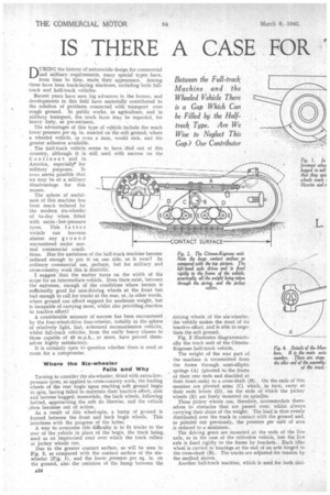
Fig. 2 illustrates diagrammatically the track unit of the CitroenKegresse half-track vehicle.
The weight of the rear part of the machine is transmitted from the frame through semi-elliptic springs (A) (pivoted to the frame at their rear ends and shackled at their front ends) to a cross-shaft (B). On the ends of this member are pivoted arms (C) which, in turn, carry at their ends levers (D), on the ends of which the jockey wheels (E) are freely mounted on spindles.
These jockey wheels can, therefore, accommodate themselves to obstacles that are passed over, whilst always carrying their share of the weight. 'The load is thus evenly distributed over the track in contact with the ground and, as pointed out previously, the pressure per unit of area is reduced to a minimum.
The driving gears are mounted at the ends of the live axle, as in the case of the orthodox vehicle, but the live axle is fixed rigidly to the frame by brackets. Each idler wheel is carried in bearings at the end of an arm hinged to the cross-shaft (B).' The tracks are adjusted for tension by the method shown.
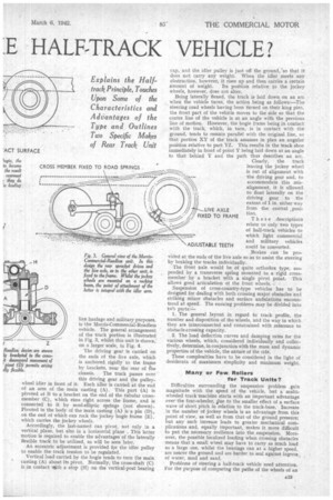
Another half-track machine, which is used for both civi lian haulage and military purposes, is the Morris-Commercial-Roadless vehicle. The general arrangement of the track portion is illustrated in Fig. 3, whilst this unit is shown, on a larger scale, in Fig. 4.
The driving gear is carried on the ends of the live axle, which is anchored rigidly to the frame by brackets, near the rear of be
chassis. The track passes over this driving gear and the pulleywheel idler in front .of it. Each idler is carried at the end of an arm of the main casting (A). This part (A) is pivoted at B to a bracket on the end of the tubular crossmember (C), which runs right across the frame, and is connected to it by semi-elliptic springs (not shown). Pivoted in the body of the main casting (A) is a pin (D), on the end of which can rock the jockey bogie frame (E), which carries the jockey wheels.
Accordingly, the last-named can pivot, not only in a vertical plane, but also in a horizontal plane . This latter motion is required to enable the advantages of the laterally flexible track to be utilized, as will be seen later.
An eccentric adjustment is provided for the idler pulley to enable the track tension to be regulated.
Vertical load carried by the bogie tends to turn the main casting (A) about its pivot. Normally, the cross-shaft (C) is in contact iith a stop (H) on the vertical-post bearing
cap, and the idler pulley is just off the ground, 'so that it does not carry any weight. When the idler meets any obstruction, however, it rises up and then carries a certain amount of weight. Its position relative to the jockey wheels, however, does not alter.
Being laterally flexed, the track is laid down on an arc when the vehicle turns, the action being as follows:—The steering road wheels having been turned on their king pins, the front part of the vehicle moves to the side so that the centre line of the vehicle is at an angle with the previous line of motion. However, the bogie frame being in contact with the track, which, in turn, is in contact with the ground, tends to remain parallel with the original line, so that portion XY of the track assumes in plan an angular position relative to part YZ. This results in the track shoe immediately in front of point Y being laid down at an angle to that behind Ir and the path thus describes an arc. Clearly, the track leaving the jockey wheel is out of alignment with the driving gear and, to accommodate this misalignment, it is allowed to float laterally on the driving gear to the extent of 1 in. either way from the central position. LIVE AXLE FIXED TO FRAME These descriptions relate to only two types of half-track vehicles to which light commercial and military vehicles could be converted.
Brakes can be provided at the ends of the live axle so as to assist the steering by braking the tracks individually.
The fi-ont axle would be of quite orthodox type, suspended by a transverse spring mounted to a rigid crossmember by a bracket with a single pivot point. This
allows good articulation of the front wheels. '
Suspension of cross-country-type vehicles has to be designed for dealing with both crossing major obstacles and striking minor obstacles and surface undulations encountered at speed. The ensuing problems may be divided into twb parts: 1. The general layout in regard to track profile, the number and disposition of the wheels, and the way in which they are interconnected and constrained with reference to obstacle-crossing capacity.
2. The load deflectidn curves and damping rates for the various wheels, which; considered individually and collectively, determine, in conjunction with the mass and dynamic properties of the vehicle, the nature of the ride.
These complexities have to be considered in the light of desiderata of maximum simplicity and minimum weight.
Many or Few Rollers for Track Units?
Difficulties surrounding the suspension problem gain magnitude with the speed of the vehicle, but a multiwheeled track 'machine starts with an important advantage over the four-wheeler, 4lue to the smaller effect of a surface wave of short pitch in relation to the track-base. Increase in the number of jockey wheels is an advantage from this point of view, as well as from that of the ground pressure; but any such increase leads to greater mechanical complications and, equally important, makes it more difficult to put the necessary resilience into the suspension. Moreover, the possible localized loading when crossing obstacles means that a small wheel may have to carry as much load as a large one, whilst the bearings ran at a higher speed, are nearer the ground and are harder to seal against ingress of water, mud and sand.
Problems of steering a hall-track vehicle need attention. For the purpose of comparing the paths of the wheels of an
ordinary wheeled vehicle with those of the half-track machine, see,Fig. 5, Consider the front. wheels of the former type, when they are locked over ; the off-side wheel takes path A, and the near-side wheel. path B; now the rear wheels take, respectively, paths C and D, all four centring about point X. When tracks are fitted, however, they -tend to go straight-ahead, so that When they are compelled to follow the paths C and D, considerable side-slip occurs.
The differential will play a useful part in helping the outfit aroundthe bend, but, except for curves of long radius, further aid is needed and brakes have to be employed. These will have to operate individually for steering purposes, and this seems to suggest that they should be connected to the steering drop arm, lost-motion links being incorporated in the operating gear.
Already, however, strafing is heavy enough, and it cannot be lightened, by taking weight off the front axle, which is probably loaded as lightly as possible, as it is, on
the score of soft ground. The limit to reducing frontwheel loading is fixed by the adhesion needed to persuade the rear tracks under easy conditions to divert from their natural straight course,
The brakes should never be allowed to lock themselves. If they did, referring again to Fig. 5, the tracks would pivot about a point and, due to the greater portion of the weight of the vehicle being on the rear, the front-axle wheels would be swung sideways, sliding along paths E and F.
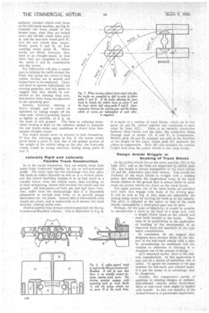
Laterally Rigid and Laterally . . ...Flexible Track Construction As to the tracks themselves, they are usually made from metal links connected together by pin or ball-and-socket joints. The latter type' has the advantage that they allow the track. to deflect laterally as Well as in a vertical plane, and this lateral flexibility enables it to be laid down 'in a circular cberse when the vehiele turns, thus 'avoiding, 'or at least minimizing, lateral skid between the tracks and the ground: All link-joints—Of both pin and bali type—however, suffer froth. the disadvantage that it is impossible adequately to exclude mud from, or to provide proper lubrication 'for, the joints. Lateral skid is unatmidable with simple pin joints, and is undesirable as it stresses the track severely, causing undue ,wear. • There is another type of track which is used with the MorrisCommercial-Roa,dless vehicles. This is illustrated in Fig. 6.
It is made of a number of track blocks, which are in two 'parts (A and B), bolted together and connected to each other by links (CC). . There. is no .metalliie connection bettveen these blocks and the links, the connection being through pads of rubber (0, E and F) in Compression. Rubber pads (D and E) transmit any pull in the direction of the 'length of the track, whilst pads (F) maintain the others in compression. Pads (El) also transmit the vertical weight load from the jockey wheels to the track bloCks,
Design Avoids Wriggle or Snaking of Track Blocks
As the jockey wheels run on the outer portions (I-I) of the links (CC), and 'as the links are supported by rubber pads (E), the weight is always transmitted to the track block's (A and 13), somewhere near their centres. This avoids the tendency of the track blocks to wriggle with a snaking action and eliminates the longitudinal, creep of the track blocks relative to the ground 'that is always liable to occur when the jockey wheels run direct on the track block's.
The upper portions (A) of the track blocks are provided withteeth that engage with thoSe of the driving gear. It will be seen in' Fig. 3, :that. these are adjustable, the setting being varied by moving the teeth in or out radially. The pitch is adjusted at the outset to that' of the track blocks; subsequently 'a fixed pitch gear can be used..
Perhaps, for the sake of simplicity, it would be possible to manufacture a track in the form of a„ large tyre, with
• a deeply' ribbed "tread on the outside and steel teeth bonded to the inside., seem ..to be possibilities in the application of bonding to the development of an improved ti-aek for Machines of the type
under consideration.
In conclusion, let me. suggest that designers -have' another think on the subject of the half-track-vehicle with a -View 'to .reconsidering .itsusefulness and the wisdom. or' otherwise of allowing if to disappear out of the.scheme of things.
As 1 remarked earlier, there-is"the military consideration. In this application it may not be a matter of Usefulness; but of safety. To ignore-the ekistence of the gap between the full-track and wheeled types, if it put the enerey at an advantage, may
be dangerous. •
• Further, the comparative merits of applying to existing designs . of ordinary four-wheeled vehicles either front-wheel drive Of reprr-track units might be studied with 'benefit. In this war mobility of the Armed forces is of paramount importance.