


HEAT CONTROL FOR RADIATOR SHUTTERS.
Page 72
If you've noticed an error in this article please click here to report it so we can fix it.
A It6surn'e' of Recently Published
Patent .Specifications7 TilE efficient control of the temperatitre of an engine may not be C0/1.5idered essential in commercial vehicles of the kind which are intended for the carrying of goods, but for those vehicles which are designed for the carrying of passengers it is essential that the engine should run smoothly so soon as the vehicle begins its journey, as popping and weak running immediately after starting are likely to create a bad impression upon passengers and to tend to destroy their confidence in the vehicles.
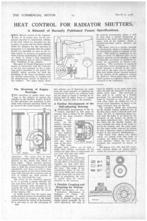
The name of Joseph•Hig,ginson is well known in connection with the Autovae, so we are not surprised to see a practical device described in his patent No. 28'2,977, which provides for -.both the , throttling of the water circulation until the desired temperature is reached and the simultaneous control of shutters to the radiator. The upper figure shows
The Mounting of Engine Bearings.
THE 'mounting of engine main bear ings is the subject of patent No. 284,433, by Sir Herbert Austin, K.B.E. In this invention the crankcase is provided with enlarged openings which can be bored in the usual manner to ensure
alignment. The centre line of these openings coincides with the edges as indicated by the ,dotted line which we have added. These enlarged openings receive housingsWhich act as bushes and caps to hold the actualbearin,,'s of the ermikshaft, and these are held in their places by means of long bolts which. may pass right through the crankcase and, as well as holding the bush portion in -place, the bolts hold the. cups.
The object of the invention appears to be to provide a means whereby the cap and lower half of the hearing are Located laterally with accuracy by 'arranging the split of the bearing (A) so that it conies slightly above the centre of the bearing (B). •
It would appear that the upper part of the housing cannot be machined truly' with its bore by turning, as the bosses extend .beyond the, radius of the housing.. It is not easy to see the advantage of
1346
this scheme, as, if departurebe made from the usual practice of splitting the bearing at the centre, an ordinary bush can be made to locate a bearing by allowing half of either brass to engage with the opposite half of the housing.
A Further Development of the Seff-adjusting Bearing. A. FURTHER development of the in vention described in this page on January 31st is shown in the specification of the same.. inventor, Friedrich IfolIman, of
Wetzlar, Get many. In the present instance, however, the self adjusting device takes the form of two washers or +distance collars which lie be tween the nut and the inner cone of the beat ing. The holes through these collars are of such a shine that sliding movement of the collars can take place to compensate for any wear that may take place in time in the bearing.
A coiled spring surrounds the two collars as shown, and has the effect of drawing them together so that they bear with a slight pressure against the cone. The angle of the contracting faces of the collars is so slight that pressure against them will not have the effect of permitting the cone to recedefrom its correct position in the bearing. • A Flexible Coupling and Mounting for Pinions.
THE specification of Con structions Electriques de Belgique of Liege, No. 273,834, deseribes a novel form of flexible coupling for shafts .which normally lie in axial alignment, but may at the general arrangement, where it will he seen that a special thermostat is situated in the water pipe leading to the upper tank of the radiator, whilst a • vacuum-controlled piston operates the shutters.
The lower view' is a section through the therthostat, where a C-shaped piece of thermostatic metal is exposed • to 'the water. This metal is composed of two strips of metal of different ratio of expansion securely joined together, so-that considerable movement is produced between its extremities at various temperatures. This movement is employed to transmit rotary movement to a-shaft which operates a throttle in the water pipe and at the same time 'to operate a plug cock which allows vacuum induced by the suction of the engine to control, the shuttersBevel gears and A flexible shaft operate an indicator which can he attached to the dashboard.
times he slightly at an anglewith, each other through the distortion of the parts • which carry them. The invention is also said to' be useful as a flexible mounting for gearwheels that may at times he required to run in mesh with each other while the shafts are not in correct axial alignment, as shown in the . upper sectional view on the left The members which are connected by* the flexible bushes employed are, in the first place, made a close fit with each other, the line of separation being central with the holes to be bored for the reception of the bushes, as shown in the upper right-hand view. After boring the holes for the flexible bushes, the inner member has some of the metal re• moved by turning, and the outer member has some -metal removed bY boring, so that a clearance space is prbduceci to permit of the required misalignment.
The Tower view shows two shafts „ which are -joined with this -form of coupling, the shafts each carrying. an inner menthes,: whilst the two outer ineinhers' are connected by means of
bolts. • .
The figures (A), (B) and (C) represent various forms of spring bushes Which the inventor proposes to employ'. '