


How a Motorvan Works.
Page 4
Page 5
If you've noticed an error in this article please click here to report it so we can fix it.
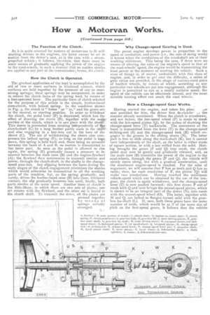
The Function ol the Clutch.
As it is quite unusual for makers of motorvans to fit selfstarting devices to the engines, the hatter cannot be set in motion from the driver's seat, as is the case with a steampropelled vehicle; it follows, therefore, that there must be some means of gradually applying the power of the engine to the road-wheels, in such a manner that no sudden shocks are applied to any part of the transmission; hence, the clutch.
How the Clutch is Operated.
The gradual application of the load is accomplished by the aid of two or more surfaces in frictional contact, which surfaces are held together by the pressure of one or more strong springs these springs may be compressed, in order to relieve the Clutch faces of the spring load, by means of a foot-operated lever. The particular form of clutch selected for the purpose of this article is the simple, leather-faced cone-clutch, with helical spring. In the condition shown in Fig. 3, the clutch is " home" pt" in," and the gears are in the neutral, or starting position. In order to withdraw the clutch the pedal lever (F) is depressed, which has the effect of ,drawing the sleeve (B), together with the mahke portion of the clutch, which is in one piece with the sleeW This sleeve is prevented from rotating independently of 11.40 clutch-shaft (C) by a long feather partly sunk in the shifft and also engaging in a key-way cut in the bore of the sleeve (C). The act of withdrawing the sleeve also compresses the helical spring (F); so long as the pedal is kept down, this spring is held back and, there being no pressure between the faces of A and B, no motion is transmitted to the Latter part. As soon as the pedal is allowed to rise again' the spring (E) gradually causes a pressure to be exerted between the male cone (B) and the engine-flywheel (A); the flywheel then commences to transmit motion and power, through the dutch-shaft, to the shafts in the changespeed gear-box. Any slipping between the faces during the early stages of the clutch engagement minimises the shocks which would otherwise be transmitted to all the working parts of the machine but, as the spring gradually, and surely, drives the leather-faced cone (B) into close, frictional contact, the slip gradually becomes less until, finally, both parts revolve at the same speed. Another form of clutch is the Hele-Shaw, in winch there are two sets of plates ; one set rotates with the flywheel, and the other set is keyed to the clutch shaft. To transmit the drive, all the plates are pressed together by means of springs suitably arranged. Why Change-speed Gearing is Used.
The petrol engine develops power in proportion to the speed of revolution, and power (i.e., the rate of doing work), is lowest when the revolutions of the crankshaft are at their working minimum. This being the case, if there were nomeans of altering the ratio of the engine's speed to that of the road-wheels speed, the engine would be transmittingthe least povver at the moment of starting the vehicle. Such a. state of things is, of course, undesirable with this class of engine, and, in order to get over the difficulty, a series of gear ratios are provided, in the shape of various-sized pairs of toothed wheels, by means of which, according as any particular two wheels are put into engagement, although theengine is permitted to run at a nearly uniform speed,the speed of the vehicle can be effectively altered, and the most. suitable turning effort can reach the road wheels.
How a Change-speed Gear Works.
Having started the engine, and taken his plact
seat provided for him, the driver first de-clutche-. themanner already mentioned. When the clutch is witndrawn, and not before, the low-speed wheel (P) is made to mesh with the low-speed pinion (Q), by the action of drawing the change-speed lever (T) backwards. The movement of the hand is transmitted from the lever (T) to the change-speed striking-rod (5) and the change-speed fork (R) which engages in the groove in the sliding sleeve (N). The latter part is free to slide along the main-shaft (K), but it cannot turn independently of the shaft, as the latter is either made of square section, or with a key milled from the solid. Having brought the gears (P and Q) into mesh, the clutch pedal may now be gently and gradually released, and, asthe male cone (B) transmits the power of the engine to the road-wheels, through the gears (P and Q), the vehicle will slowly move along, but with a gradual acceleration, until the maximum engine-speed is reached. For the sake of argument, we will assume that P has 40 teeth and Q has 20 teeth; then, for each revolution of P, the pinion (Q) will make two revolutions. Having reached the maximum. vehicle-speed which can be obtained by the use of the lowgear, the clutch is again withdrawn, and the change-speed, lever (T) is now pushed forward : this first draws P out of mesh with Q and next brings the second-speed pinion, which is shown to be an integral part of the sleeve (N), into mesh with the second-speed wheel (0). The latter, together with M and Q, are bolted to flanges turned solid with the gearbox lay-shaft (L). If, now, both these gears have the same number of teeth, which would be 30 if of the same size of pitch as the first-speed gears, it follows that the vehicle -would run at twice the previous speed, assuming that the engine speed is the same, as the tvcr shafts now run one to one. Another change of gear-ratio-may be obtained by again de-clutching, and sliding the sleeve (N) further forward by the aid of the change-speed lever. The first part of the motion withdraws the toothed portion of N out of mesh with 0, and a further movement causes the jaws projecting from N to engage with similar jaws projecting from the pinion (j). This latter part, which is positively driven by the male portion of the clutch, is now positively clutched to the sleeve (N); the main-shaft (K), and the clutch shaft (C), therefore, revolve at the same speed, or what is known as direct (or through) drive on top-speed. The lay-shaft (L) is meanwhile being caused to rotate idly, by reason of the meshing-, of the ring (M) with J. A much higher driving efficiency is thus obtained on top-speed, than is the case when J drives M, and Q (on the same shaft as M) is driving P on the main shaft.
The gear-box illustrated is fairly representative of the average three-speed-and-reverse type, although many modifications are made with the object of decreasing the lengths of the shafts and the travel of the change-speed lever. The reverse pinion is not shown in Fig.3, for reasons of simplicity, but this is simply a broad-toothed pinion, which is caused to mesh with P and 0 at the same time, the latter 3.rs then " mating " through it and not directly. It w. tdily be understood that the introduction of another
whe -11:o the train of gears brings about a change in the
direction of rotation of the last wheel.
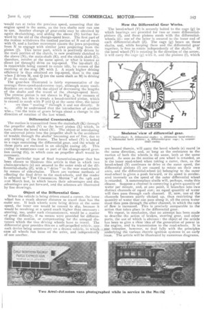
Differential Countershaft.
The motion is transmitted from the Mainshaft (K) through the propeller shaft (V) to the bevel pinion (X) which, in turn, drives the bevel wheel (Y). The object of introducing the universal joints into the propeller shaft is the avoidance of trouble through the shafts' becoming out of line, due to any twisting of the frame. The bevel wheel (Y) is bolted to a cage containing the differential gear, and the whole of these parts are enclosed in an oil-tight casing (d). This casing is sometimes cast as part of the change-speed gearbox casing (G), in which case no propeller shaft would be necessary.
The particular type of final transmission-gear that has :been chosen to illustrate this article is that in which two .chain-sprockets (a) are secured to the outer ends of the differential-shafts (Z), with a " drive " to the rear road-wheels
.by means of side-chains. There are various methods of effecting the final drive to the road-wheels, and the reader is referred to "THE COMMERCIAL MOTOR " of the Llth and 21st March last, in which issues their advantages and disadvantages are put forward, and the schemes are illustrated by line drawings.
Object of the Differential Gear.
When the vehicle is being driven round a corner, the_inne-r wheel has a much shorter distance to travel than has the outer one. If both wheels were being driven at the same speed, the inner one would be caused to slip, because it would be revolving at a speed much higher than necessary : .steering, too, under such circumstances, would be a matter of great difficulty, if no means were provided for differentiating the motion, or compensating for the unequal distances which the two driving wheels have to travel. The differential gear provides this on a self-propelled vehicle, any-. such device being unnec.ess:ary on a drawn vehicle, in which,:e case• all wheels run loose on The axles, and independently of one another. How the Differential Gear Works.
The bevel-wheel (Y) is securely bolted to the cage (g) in which bearings are provided for two or more differentialpinions (f), and these pinions mesh with the differentialwheels (e): one of the latter is secured to the inner end of each differential-shaft (Z). The cage (g) bears on these shafts, and, while keeping them and the differential gear together, is free to rotate independently of the shafts. If the bevel wheel (Y) is rotating in the direction of the arrow, it will carry the cage (g) with it, and the pinions (f), which are housed therein, will carry the.bevel wheels (e) round irr the same direction, and, so long as the. resistance to the motion of both the wheels is the same, both at the same speed. As soon as the motion of one wheel is retarded, as is the inner road-wheel when taking a curve, then, as the bevel-wheel (Y) continues to drive at the same speed, the differential pinions (f) are caused to rotate on their own axes, and the differential-wheel (e) belonging to the outer road-wheel is given a push forward, or its speed is accelerated inversely as the speed of the outer differential wheel is retarded. A commonplace simile will, perhaps, make this clearer. Suppose.a channel is conveying agiven quantity of water per minute, and, at one point, it branches-into-two distinct channels of equal size; an equal quantity of water will then pass through each channel. If, now, one of the channels becomes partly -choked. up, thus restricting the quantity of water that can pass along it, all the extra water must then pass through the other, channel, in which the rate of flow is increased. This is precisely comparable to the action that takes place in the differential gear.
We repeat, in conclusion, that no attempt has been made to describe the action of brakes, steering gear, and other parts, the use of which is obvious : the object of the article has been to give a clear idea of the generation of power in the engine, and its transmission to the road-wheels. It is r :intention, however; to deal fully with the principles Underlying the various electric ignition systems in an early issue The article will he illustrated by numerous diagrams