


An Unusual Design of Clutch
Page 66
If you've noticed an error in this article please click here to report it so we can fix it.
PATENT No. 410,380 describes a new form of friction clutch for which several advantages are claimed, chief amongst them being lightness of operation compared with the forces controlled. The patentee is Gustave Fast Engineering Corporations Annapolis, Maryland, U.S.A.
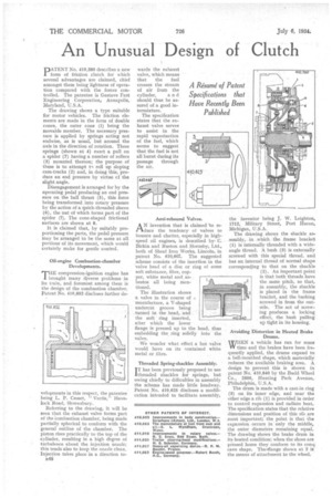
The drawing shows a type suitable for motor vehicles. The friction elements are made in the form of double cones, the outer cone (1) being the movable member. The necessary pressure is applied by springs acting not endwise, as is usual, but around the axis in the direction of rotation. These springs (shown at 4) exert a pull on a spider (7) having a number of rollers (3) mounted thereon; the purpose of these is to attempt t.-) roll up sloping cam-tracks (2) and, in doing this, produce an end pressure by virtue cf the slight angle.
Disengagement is arranged for by the operating pedal producing an end pressure on the ball thrust (5), this force being transformed into rotary pressure by the action of a quick-threaded sleeve (6), the nut of which forms part of the spider (7). The cone-shaped frictional surfaces are shown at 8.
It is claimed that, by suitably proportioning the parts, the pedal pressure may be arranged to be the same at all portions of its movement, which would certainly make for gentle control.
Oil-engine Combustion-chamber Developments.
TIIE compression-ignition engine has brought many rcliverse problems in its train, and foremost among them is the design of the combustion chamber. Patent No. 410,852 discloses further de
velopments in this respect, the patentee being L. P. Croset, " Vectis," Havelock Road, Shrewsbury.
Referring to the drawing, it will be seen that the exhaust valve forms part of the Combustion chamber, being made partially spherical to conform with the general outline of the chamber. The piston rises practically to the top of the cylinder, resulting in a high degree of turbulence about the injection nozzle; this tends also to keep the nozzle clean. Injection takes place in a direction to 148 wards the exhaust valve, which means that the fuel crosses the stream of air from the cylinder, a n d should thus be assured of a good intermixture.
The specification states that the exhaust valve serves to assist in the rapid vaporization of the fuel, which seems to suggest that the fuel is not all burnt during its passage through the air.
Anti-rebound Valves.
AN invention that is claimed to reduce the tendency of valves to bounce and chatter, especially in highspeed oil engines, is described by, C. Birkin and Ruston and Hornsby, Ltd., both of Sheaf Iron Works, Lincoln, in patent No. 410,467. The suggested scheme consists of the insertion in the valve head of a disc or ring of some soft substance, fibre, copper, white metal and asbestos all being mentioned.
The illustration shows a valve in the course of manufacture, a V-shaped undercut groove being turned in the head, and the soft • ring inserted, after which the lower flange is pressed up to the head, thus embedding the ring solidly into the valve.
We wonder what effect a hot valve would have on its contained white metal or fibre.
Threaded Spring-shackles Assembly. IT has been previously proposed to use 'threaded shackles for springs, but owing chiefly to difficulties in assembly the scheme has made little headway. Patent No. 410,625 discloses a modification intended to facilitate assembly,
the inventor being J. W. Leighton, 1712, Military Street, Port Huron, Michigan, U.S.A. "
The drawing shows the shackle assembly, in which the frame bracket (1) is internally threaded with a wideangle thread. A hush (3) is externally screwed with this special thread, and has an internal thread of normal shape corresponding to that on the shackle (2). An important point is that both threads have the same pitch, so that, in assembly, the shackle is placed in the frame bracket, and the bushing screwed in from the outside. The act of screwing produces a kicking effect, the bush pulling up tight in its housing.
Avoiding Distortion in Heated Brake Drums.
WHEN a vehicle has run for some 11/ time and the brakes have been frequently applied, the drums expand to a bell-mouthed shape, which materially reduces the available braking area. A design to prevent this is shown in patent No. 410,840 by the Budd Wheel Co., 2500, Hunting Park Avenue, Philadelphia, U.S.A.
The drum is made with a cast-in ring (3) on its inner edge, and near the other edge a rib (1) is provided in order to control expansion and radiate heat. The specification states that the relative dimensions and position of this rib are most important; the point is that the expansion occurs in only the middle, the outer diameters remaining equal. The drawing shows the brake drum in its heated condition; when the shoes are pressed home they conform to its con.;. cave shape. Theirflange shown at 2 is the means of attachment to the wheel.