


Patents Completed.
Page 20
If you've noticed an error in this article please click here to report it so we can fix it.
Bleriot Electrical Equipment. Steering of Traction Engines. Detachable Auxiliary Rims. Spring-Wheel Construction.
Soc. DES ETABLISSEMENTS •L. BLERIOT, No. 8466, 1915, dated tinder International Convention 25th July, 1914.—This invention provides an improved construction of dynamo and arrangement of circuits on a vehicle, when a dynamo and
battery are used in conjunction with one another. The dynamo has a shunt-winding and a reversed series-winding which is in two parts. The smaller part of the series winding is connected, in series with the main current-consuming devices, such as the horn and the headlights, -while the larger part, or whole of the series winding, is connected with the smaller lamps and in the battery circuit. A resistance may be arranged permanently in series with the shunt-field, and the controlling switches for the large gwrent-consurning devices may be coupled to additional switches which cut out a whole or part of this resistance when it is desired to take a large current from the dynamo. The usual cut-outs and automatic control are provided for the circuits, and the whole arrangement ensures that the battery cannot be overcharged by the dynamo and that no matter at what speed the dynamo may be run, it cannot send an excessive current through any of the fittings.
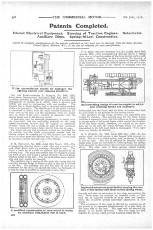
P. H. BattLimm, No. 4626, dated 24th March, 1915.—The accompanying drawing shows a side view and a section of a
road wheel fitted with' an auxiliary detachable rim. The wheel is built up of a solid Or skeleton disc mounted in an ordinary hub. The main rim portion may be arranged to take any kind of tire, and it has a central inwardly directed flange which is bolted to the disc. The rim is therefore easily detachable and may readily be changed.
The auxiliary rim is similar to the main rim except that its inwardly directed flange is dished so that it also can be bolted to the disc. The auxiliary rim and tire may be used as a substitute for the main tire should the.latter be damaged, or it may lie kept in position to constitute a twin wheel.
F. B. DEux (Bur,Locx Tu...i.croit Co.), No. 11,828, dated 16th August, 1915.—The accompanying drawing shows a partial plan view of a traction engine of the type having endless selflaying tracks. According to this invention, the steering of such an engine is effected jointly by means of steering wheels in the front and varying the relative speeds of the two tracks. The transmission gear of the vehicle is arranged with the differential near the front, and the drive is transmitted back by side chains to the pinions for the endless tracks. The sprockets at the front, however, are separately controlled by clutches. The steering gear for the front wheels includes a segmental rack, and two rollers on it are arranged to engage arms of bell-crank levers which control the clutches. When the front wheels, therefore, are turned in one direction, say to the left, the clutch through which the drive is transmitted to the left-hand track is disengaged. Very rapid turns can thereby be effected.
Cl. J. MURPHY, No, 7991, dated 29tb. May, 1915.—In this spring wheel the hub carries a rim formed with grooved recesses. The tire is' a coiled spring, and, as shown, is shaped to run on rails. The tire is retained by laterally inclined radial links which are connected to coiled springs., the springs being mounted on pins lying in the grooved recesses mentioned above. The other ends of these springs extend radial y inwards and abut an set-screws in two rings surrounding the hub. These rings are mounted on threaded studs, so that they can be adjusted towards or away from one another, while the set screws permit individual adjustment of each spring.
The adjustment of the rings is effected by coupling-up all the, screws to be operated simultaneously by a gear fixed on the inner side of the hub. This gear may be adapted for manual or for power operation. The two rings are tied together by springs which prevent looseness being set up.