


Worm-Driven Axles.
Page 6
If you've noticed an error in this article please click here to report it so we can fix it.
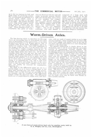
The line drawing which we reproduce on this page shows an interesting form of worni-driven live !melt axle of particularly strong construction ; it has been designed and built by FL. G. Wrigley and Co., Ltd., of Foundry Lane Works, Soho, Birmingham, and is intended for omnibus work. One's first impression of the design is that the axle is on the heavy side, and we learn that it weighs, complete, about bi cwt. In this matter, the makers have followed the inclination of their client rather than their own. Of the workmanship which has been put into this axle by its makers, the excellent materials of which it is made, and the ample proportion of all its parts, there can hardly be two opinions ; it is well calculated to stand up to hard wear in prolonged service. The centre casing is of malleable-cast iron, and is split both through the centre and along the axis of the worm shaft, so that the latter shaft, together with its bearings, can readily be removed for examination, cleansing, etc.
The teeth of the differential gears are cut to a special shape, so as to leave a strong base, at the same time insuring easy and silent rolling motion. Timken roller or ball bearings are provided for all the journals, with the exception of the differential pinions within the planetary cage. The differential shafts are of ample-diameter nickel steel, and their
outer ends are made of square section so as to take driving couplings; these couplings are provided with teeth which engage with similar teeth in the hub of the wheel, and also with teeth in an inner lining that is fitted to the wheel hub.
The general construction is clearly shown in the illustration, and it will be noted that the up-to-date practice of transmitting torsional stresses only through the differential shafts has been followed. All the bending stresses are sustained by the solid-drawn weldless steel tubes which, at their outer ends, are turned to take the Timken bearings, whilst tkeir inner ends are expanded to conical shape and are provided with flanges that are bolted to similar flanges on the malleable cast centre casing. The spring seats and brake-anchor brackets are welded to the steel tube by the oxy-acetylene process. The brake arrangement is well worthy of notice: the drum, which is of steel, is pressed into a U-section ring ; two sets of expanding brakes are fitted, one of these being operated by a pedal, the other by a side lever. The foot lever operates the smaller of these expanding brakes, which are of the metal-to-metal type. The shoes within the larger diameter of the brake drum are operated by means of a hand lever, and the brake shoes may be faced with Ferodo or other suitable material.