


COOLING THE MAIN BEARINGS OF CRANKSHAFTS.
Page 28
If you've noticed an error in this article please click here to report it so we can fix it.
A Resume of Recently Published Patent Specifications.
il ITHERTO little attention has been
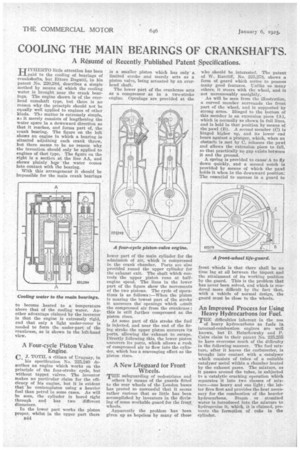
paid to the cooling of bearings of crankshafts, but Ettore Bugatti, in his patent No. 220,284, describes a simple method by means of which the cooling water is brought near the crank bearings. The engine shown is of the overhead camshaft type, but there is no reason why the principle should not be equally well applied to engines of other kinds. The matter is extremely simple, a t it merely consists of lengthening the water spare in a downward direction so that it reaches, and forms part of, the crank bearing. The figure on the left shows an engine in which a bearing is situated adjoining each crank throw, but there seems to be no reason why the invention should only be applied to engines of that type. The figure on the right is a section at the line AA, and shows plainly hey the water comes into contact with the bearing.
With this arrangement' it should be impossible for the main crank bearings to become heated to a temperature above that of the cooling water. Another advantage claimed by the inventor is that the engine is extremely rigid, and that only a light under-cover is needed to form the under-part of the crankcase, as is shown in the left-hand view.
A Four-cycle Piston Valve Engine. C. J. TOTH, a citizen of Uruguay, in his specification No. 225,240 describes an engine which works on the principle of the four-stroke cycle, but without tappet valves. The inventor makes no particular claim for the efficiency of his engine, but it is evident that hecontemplates using a heavier fuel than petrol in some cases. As will be seen, the cylinder is bored right through and has two different diameters.
in the lower part works the piston proper, whilst in the upper part there B44 is a smaller piston which has only a limited stroke and merely acts as a piston valve, being actuated by an overhead shaft.
The lower part of the crankcase acts as a compressor as in a two-stroke engine. Openings are provided at the lower part of the main cylinder for the admission of air, which is compressed in the crank chamber. Ports are also provided mind the upper cylinder for the exhaust exit. The shaft which controls the upper piston runs at halfengine /Speed. The lines in the lower part of the figure show the movements of the two pistons. The cycle of operations is as follows :—When the piston is nearing the lowest part of the stroke it uncovers the openings which admit the compressed air from the crankcase ; this is still further compressed as the piston rises.
At some part of this stroke the fuel is injected, and near the end of the firing stroke the upper piston uncovers its ports, allowing the -exhaust to escape. Directly following this, the lower piston uncovers its ports, which allows a rush of compressed air to flow into the cylinder, which has a scavenging effect as the piston rises.
A New Lifeguard for Front Wheels.
THE safeguarding of nedestrians and others by means of the guards fitted to the rear 'wheels of the London buses has proved so successful that it seems rather curious that so little has been accomplished by inventors in the devising of some workable guard for the front wheels.
Apparently the problem has been given up as hopeless by many of those who should be . interested. The patent of W. Ratcliff, No. 225,278, shows a form of guard which seems to possess many good features. Unlike so many others, it steers with the wheel, and is not unreasonably unsightly.
As will be seen from the illustration, a curved member surrounds the front part of the Wheel, and is supported by strong arms. Hinged to the bottom of this member is an extension piece (A), which is normally as shown in full lines, and is held in that position by means of the pawl (B). A second-member (C) is hinged higher up, and its lower end bears against a plunger, which, when an obstacle is met by C, releases the pawl and allows the extension piece to fall, so that practically no gap exists between it and the ground.
A spring is provided to cause A to fly down quickly, and a second notch is provided by means of which the pawl holds it when in the downward position: The essential to success in a guard to front wheels is that there shall be no time lag at all between the impact and the attainment of its working position by the guard. This is the problem that has never been solved, and which is rendered more difficult by the fact that, with a vehicle of normal design, the guard must be close to the wheels.
An Improved Process for Using Heavy Hydrocarbons for Fuel.
THE difficulties inherent in the use of heavy hydrocarbons as fuels in internal-combustion engines are well known, but D. Balachowsky and P. Caire claim in their patent No. 225,255 to have overcome much of the difficulty in the following manner. The fuel mixture, after it leaves the carburetter, is brought into contact with a catalyser which consists of tubes of a suitable catalyser metal within a chamber heated by the exhaust gases. The mixture, as it passes around the tubes, is subjected to a catalytic cracking operation which separates it into two classes of mixture—one heavy and one light ; the latter fires first and provides the heat necessary for the combustion of the heavier hydrocarbons. Steam or atomized water is introduced into-the mixture to hydrogenize it, which, it is claimed, prevents the formation of coke in the cylinder.