


Combining Direct and Indirect
Page 36
If you've noticed an error in this article please click here to report it so we can fix it.
Injection
A COMBUSTION scheme for oil CA engines, claimed to possess the advantages of both direct injection and ante-chamber injection is shown in patent No. 541,552 by D. Oram, Knighton Hall, Knighton, Leicester.
In effect there are two chambers connected by a narrow passage in which the nozzle is located. The major chamber (1) is located in the cylinder head, whilst the Minor chamber (21 is formed partly in the head and partly in the piston.
A feature is that the last-named does not closely approach the head, but leaves a conical clearance (3). This is in contrast with the more usual arrangement which imparts a topdead-centre " squish " (the term used in the specification) to practically the last remnant of air in the cylinder.
Air in the minor chamber receives a vortex or " smoke-ring" motion, but that in the upper chamber is given a true swirl, owing to the offset of the neck. The disposition of the fuel jets, three in number, is clearly shown in the drawing.
UPPER-CYLINDER LUBRICATION FOR PRODUCER-GAS ENGINES "TO provide upper-cylinder lubrication, 1 and thereby to minimize the effect of corrosive substances contained in prcklucer gas, is the object of a scheme shown in patent No. 541,818 by W. Morison kid the Eastern National Omnibus to., Ltd., Chelmsford. The specification describes . a -device, for spraying lubricant into the induction pipe, so that it is carried directly into the cylinders.
Simplicity characterizes the apparatus. Fitted to the pipe (1) from the cleaning unit is an adjustable sightfeed oil drip (2), which supplies engine oil from a suitable tank, Engine suction draws oil into the gas pipe, where it is formed into a spray by the flow of gas. The scheme is said to be particularly applicable to the Morison producer-gas system shown in an earlier. patent, No. 541,533, which we described in a previous issue.
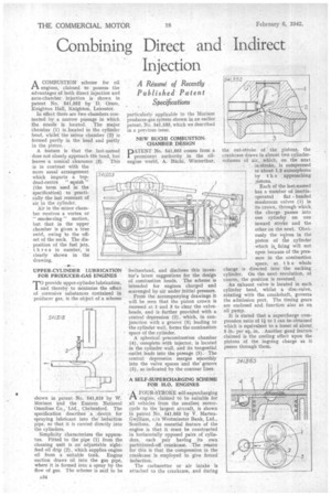
NEW BUCHI COMBUSTIONCHAMBER DESIGN •
PATENT No. 541,865 comes from a prominent authority in the oilengine world, A. Biichi, Winterthur,
Switzerland, and discloses this inventor's latest suggestions for the design of combustion heads. The scheme is intended for engines charged and scavenged by air under initial pressure.
From the accompanying drawings it will be seen that the piston crown is recessed at 1 and 3 to clear the valveheads, and is further provided with a central depression (2), which, in conjunction with a groove (5) leading to the cylinder wall, forms the combustion space of the cylinder.
A spherical precombustion chamber (4) , complete.with injector, is located in the cylinder wall, and its tangential outlet leads into the passage (5). The central depression merges smoothly into the valve spaces and the' groove (5), as indicated by the contour lines.
A SELF-SUPERCHARGING SCHEME FOR H.O. ENGINES
AFOUR-STROKE self-supercharging engine, claimed to be suitable for all vehicles from the smallest motorcycle to the largest aircraft, is shown in patent No. 541,053 by V. MartenGwilliam, c/a Westminster Bank, Ltd., Southsea. An essential feature of the engine is that it must be constructed in horizontally opposed pairs of cylinders, each pair having its own partitioned-off crankcase. The reason for this is that the compression in the crankcase is employed to give forced induction.
The carburetter or air intake is attached to the crankcase, and during the out-stroke of the pistons, the crankcase draws in almost two cylindervolumes of air, which, on the next in-stroke, is compressed to about 1.3 atmospheres by t h e approaching ?istons.
Each of the last-named has a number of inertia
operated flat headed mushroom valves (1) in its crown, through which the charge. passes into one cylinder on one inward stroke and the other on the next. Obviously the valves in the piston of the cylinder which is firing will not open because of the pressure in the combustion
space, so t h a whole charge is: directed into the sucking cylinder. On the nextrevolution, of course, the .position is reversed.
An exhaust valve is located in each cylinder head, whilst a disc-valve, rotating with the crankshaft, governs the admission port. The timing gears are enclosed and. functitm also as an oil pump.
It is stated that a supercharge compression ratio of 1ito 1 can be obtained which is equivalent to a boost of about
5 lb: per sq.. . Another good feature claimed is the cooling effect upon the pistons of the ingoing charge as it passes through them.