


Patents Completed.
Page 18
If you've noticed an error in this article please click here to report it so we can fix it.
MOTOR VEHICLE. — .Atkey. — No. 12,1142, dated 24th May, 1907.—A shaft (5), 'carried by suitable bearings (6), is arranged between the side members (a) ot the chassis. Arms (2), connected to the body of the vehicle by bolts (7), are securely mounted on the shaft (5). The shaft also carries a double, slotted lever A screw shaft (14), on one end of which an operating handle (16) is mounted, is carried by brackets (12, 13) secured to the cross bars (10, 11). A nut (15), which engages the double sluts in nthe lever (.8), is mounted on the screw shaft 04). It will be seen that rotation of the shaft (14) by means of the halidle (16) gives motion to the nut (15) and this, through the double, slotted lever (8) actuates the shaft (5) and leYers (2). These latter raise the vehicle body above the chassis, thus enabling the driving mechanism to be inspected or repaired.
LOCK NUT.—Goulding.—No. 10,331, dated 3rd May, 1907.—A washer is formed
with a central portion (a) having ashaped holehole which engages with the bolt (Lk so as to prevent the washer turning on the same. An outer ring (c) surrounds the central portion (a) and is joined to it at d. A series of notches (e) so spared that they may engage with the corners of the nut (g) are arranged on the inside of the ring (c). The ring (c) is bent up normally, as shown in Figure 1, hut when the washer is applied, the ring (e) is held fiat to allow the nut to be screwed into position, when it is allowed to spring up iato engagement with the corners If) of the nut (g). In this way the nut is securely locked.
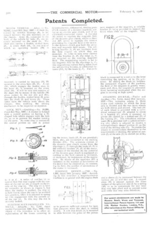
ELECTRICAT.T.Y-PROPELT.ED VEHICLE. — Albrecht. -No. 7,141, dated (under Convention) 12th May, 1901:I.—The (lbject of this invention is to effect an equalisation of the losses occurring in dynamo.electric, differential, driving gears which consist of a dynamo machine, actMg as an electric gear clutch, and of an electrically-connected motor. A rheostat (R) serves to regulate the magnetic field of the dynamo gear clutch, whilst a rheo
tat (10) serves to regulate the current generating the magnetic field of the motor. In the dynamo clutch gear both the armature and magnetic field rotate. The collecting brushes (b, 61) are insulated from the field magnet on which they are mounted. In order to take away current from the brushes (6, LT) slip rings (s, are mounted on the rotating, magnetic field. The magnetising current is led to the magnetic field by the slip rings (s, this magnetising current being taken from the self-exciting booster, or additional dynamo (Zr1), by the leads (1, /1)For excit ing the motor, leads (12, /3) are provided ; these, also, are connected to the exciting dynamo (Zd). The armature current of the dynamo gear clutch comes from the slip rings (s, s'-') through the leads (14, /5) to the collector brushes (62, 63) of the motor. By means of the rheostat (R) the potential of the dynamo gear clutch is regulated according as the field current is increased, or decreased, by resistances of the regulation. By means of the regulator (R1) a variation in the number of revolutions of the motor may be obtained as, on weakening its field, the number of revolutions of the motor is increased.
IGNITION DEVICE, —Cliff. —No, 1,301, dated 18th January, 1907.—According to this invention a magneto-electric machine is so geared with the engine shaft
as to generate sufficient c irrent for ignition purposes when the shaft is rotated slowly. A soft iron block (a) is mounted to slide between the poles of the puma nent magnets of the magneto, a suitable bracket (6) being provided to support the block when clear of the magnets. This block is connected by a rod (c) o the lever controlling the ignition, or to thegovernor. By sliding the block (a) between the permanent magnets of the machine, the field of the magnets is greatly weakened, and, thus, the magneto is prevented from becoming overloaded when the engine is running at high speed.
STEERING JOURNAL—Taylor and Another.—No. 1,555, dated .21st January, 1C07.—This invention relates to those motor road vehicles in which the front axle is divided and the two front wheels are both driven and steered. The hub (A) of each wheel is provided with a cylindrical enlargement (B) adapted to rotate in a bearing (C) which is mounted on pivots (D) carried by a forked end (E) of the framing (F). The cylindrical enlargement (B) is provided with a spherical bearing (ti), which is adapted to receive a correspondingly shaped portion (II on the end of the driving axle (G). To enable the wheels to accommodate themselves to the requirements of steering, the spherical portion (Ti of the axle (G) is slotted (as at K), and a sleeve (L) is interposed between the vertical pin (j) and this slot. A cupped plate (M) is pressed against the inner surface of the spherical end (I) by a spring (M1) so as to compensate for any wear that may take place and to prevent noise and rattle that may arise therefrom.