


Some Experiments with a Sparking Coil.
Page 16
Page 17
If you've noticed an error in this article please click here to report it so we can fix it.
The Effects on the Working Speed of the Coil, and the Temperature of the Spark, when the Primary Current is Increased in Strength.
Exactly what happens when the current in the primary circuit is increased beyond the strength necessary for the 'economical working of a coil is clearly -shown by the results of an interesting -series of experiments made recently by 'Mr. S. J. Watson, of the United Motor Industries, Limited, of Poland Street, W. The primary object of his research was to ascertain the effect produced on The trembler when the strength of the -current was increased. All tremblers are more or less sluggish in their action, but it is not generally known to what extent this evil can affect the working of a multi-cylinder coil. The usual methods of adjusting such a coil —judging by the " buzz " of the trembler, and by the appearance of the sparks at the plugs are absolutely unreliable; they do not give the slightest indication of the value of the spark, or -of its ability to ignite a charge.
In order to obtain perfect svachro
nism of all the tremblers, and to work a muiti-cylinder coil at it safe and economical rate of consumption, it is necessary to use a reliable ampere meter during the operation of adjusting the tremblers. When it is not properly .adjusted, a trembler may be so sluggish in its action that the -first spark will not pass across the points of the plug until the piston has travelled a considerable distance on its working .siroke. As the speed of the engine increases, this trouble becomes aggravated ; this is also the case when the h of the current is increased.
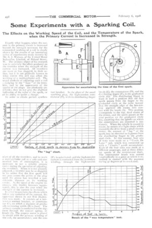
III order to ascertain the effects which follow any variation of the current, the apparatus shown ill our first illustration was. made. It consists of a lowtension contact breaker, or commutator tr 1, on which a segment of gradually-increasing width (B) is fixed. The primary current is conducted to the segment through the contact spring, or Jtrush (.1). The ampere meter is placed in circuit with the primary winding of the coil, the accumulator, and the con
tact breaker. In the place of the usual sparking plug, the high-tension commutator (D), with its distributing finger (F), is substituted, and the high-tension current is conducted from the secondary winding, through the high-tension
brush (E), the commutator (D), and the distributing finger (F), to the graduated circle (G). The distributing finger is fixed in such a position that the first spark passes from the finger to the graduated circle at the same instant that the straight edge of the low-tension segment (B) comes into contact with the brush (A). This position corresponds to the top, dead centre of the piston, .and the spark passes at the zero position on the graduated circle (C), assuming that the spindle on which the commutators are mountedis stationary. When the spindle is caused to rotate, by means of a light chain which transmits the drive from a small electric motor, the amount of " lag " of the spark may be observed as it passes from the distributing finger to the graduated circle. In this manner, four sets of tests were made on a " Castle De Luxe " coil, which was connected up with a " Castle," 4-volt accumulator. Each of the four tests was made at a different amperage, and at three different speeds of the commutator Shaft. The commutator brush was moved longitudinally to a point at which it remained in contact with the segment during 52 degrees of its revolution.
The results of these tests have been plotted on paper and are clearly shown in the chart on page 498. An examination of the four diagonals will show that the " lag " increased not only with the speed of the shaft, but also with the increase in the strength of the primary current. It will be sufficient for our purpose to take the variation of the ". lag " at one speed of the shaft, but at varying strengths of current, in order to illustrate the difference in the time at which the first spark passes. With a current of 0.75 ampere, and with the shaft running at 93or.p.m., the first spark passed from the finger to the circle at 12 degrees from the top, or zero, position ; this increased to 16 degrees with t.o ampere, 23 degrees with 1.5 amperes, and 36.0 degrees when the current was increased to 2.0 amperes. The rate of increase in the degrees of " lag " was, therefore, exactly proportional to the increase in the strength of the current.
If the tremblers of a four-cylinder coil were so adjusted that the four primary coils were taking current as follows :—No. i, o.75; No. 2, 1.O; No. 3, t.5; and No. 4, 2.0 amperes, and assuming that the engine for which the coil is used had a stroke of four inches, then all the cylinders would be firing at different times, thus: No. T., would fire at o.575; No. 2, at 0.82; No. 3, at 0.97; and No. 4 at Lis inches from the top
of the firing stroke. Such a relative condition of firing is not calculated to give good results in any engine, and it is quite probable that much of the unaccountable and had running of an engine is attributable to this cause.
Excessive consumption of current in the primary coil may cause the insulation to break down. The next chart shows the effect of passing a current of 2; amperes through a coil for a long period. It will be seen that, as the temperature increases, the length of the spark decreases. A point worth noting in connection with this test is that,
after the wax was allowed hi set again, it was found that the longest spark the coil would give was only equal to that given at the last reading, when the wax was melted. The curve on this chart shows the rate of the rise in the temperature of the Wax.
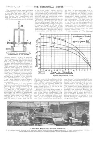
The next experiment was intended to show the relation of the spark temperature to the current consumption. For this purpose, the small instrument shown in the adjoining column was used ; it was inserted in the high-tension circuit instead of the usual spark
ing plug. It is not suggested that, by this means, the temperature of the spark is indicated, but it offers a simple and practical means of comparing the temperature, under precisely similar conditions, but at different rates of current consumption. The three curves on tile temperature chart will show that, as the rate of current consumption is increased, the rate of increase in the temperature shows a tendency to fall. The best results are obtained when the ampere meter shows a steady and equal reading for each unit.
A representative of " Tiia COMMER
CIAL MOTOR " recently examined the apparatus by the aid of which the above records were obtained, and also observed some of the tests, at the company's testing axims in Poland Street. The ampere meter ‘vhich was used for the purpose was one of a type which the company has introduced specially for this class of work. It is a dea,d-heat instrument, and is neatly finished so that it could be mounted on a dashboard, permanently in circuit, or connected, through a simple switch, with the primary circuit.