


Helical Suspension Springs on Rubber Seats
Page 34
If you've noticed an error in this article please click here to report it so we can fix it.
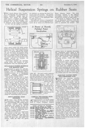
THAT Morris Motors, Ltd., Cowley. is investigating the possibilities of helical suspension springs may be inferred from patent No. 527,468, which shows a method of mounting these springs on rubber seatings. The patentees are the above concern and A. Issigonis, of the company's address.
At each end the spring is provided
with a metal washer (4) which centres itself in an inner cup (3) by means of a central boss (2). The rubber seating disc (1) is placed between the washer (4) and the frame, its position being fixed by a projecting boss fitting boss 2 and surrounding a stud on the frame. The rubber disc may be provided with annular grooves to increase its deformation under load.
: Advantages claimed are smoother spring action and. absence of noise transmitted from the unsprung parts.
DETACHABLE RUBBER BUSHINGS FOR SHACKLE PINS
DISCLOSED in patent No. 527,463, by H. Clayton-Wright and Howard Graham, Ltd., 4, Tiddington Road, Stratford-on-Avon, is a shackle-pin assembly utilizing torsion-stressed rubber as the bushing medium.
Conveniently formed from a single round bar (2), the pins are bent to a U-shape and screwed at the ends. Sideplates (1) act as an abutment for the rubber sleeves (shown shaded), and the act of tightening the nuts has the effect of swelling the rubber into gripping contact with the 'pins and the outer spring eyes, or sleeves therein.
A big advantage of the scheme, although not mentioned in the patent, is that the bushes can be replaced without having recourse to presses or other means for assembling under pressure.
SERVO-ASSISTED GEAR CHANGING OR many years Bendix Aviation Corporation, Chicago, U.S.A., has been experimenting with various forms of power assisted gear changing mechanism, and patent No. 527,437 shows its latest proposals in this connection. These are diagrammatically illustrated in the accompanying drawing of the complete layout. The ariver's control is a small knob (2) mounted on the dash. The knob has a dual motion, push and pull, and a. turning movement. The push-pull action will give, say, first speed and reverse, whilst the other two speeds are obtained by turning the knob to a second push-pull position. The spindle of the knob is governed by an H-shaped slot (1) similar to the guide-gate used on some gearboxes.
The% push-pull motion is transmitted to the valve of a suction-operated servo motor (5) by means of a Bowden-type cable (6). The servo motor performs the actual gear change. Cable 6 cannot also transmit the rotary motion, so this is conveyed by a second cable (3) which is secured to the end of an arm on the knob spindle and rocks the slide selector arm (4)
.5274e5 to one side or the other. Should the servo mechanism fail, the cables are stout enough to permit direct operation by the driver.
COMPACT TWO-STROKE WITH GOOD SCAVENGING
AN opposed-piston two-stroke engine is disclosed in patent No. 527,621 from C. Taylor, Langdale, Duffield
Road, Allestree, Derby. The chief advantage, claimed is the efficient scavenging obtained at low speeds, giving even working on light loads.
The layout is compact, due to the use of horizontal cylinders with the crankshaft below them, rockers being used to_ transmit the motion. The
pistons move in opposite directions, the combustion space being in the middle of the cylinder. The spaces (3 and 5) behind the pistons are sealed oh from the crankcase, and constitute charging pumps, being fed from ports (4).
Chamber 3 pumps fuel, mixture, which traverses pipe 1 and enters the cylinder via a piston-controlled port. Left-hand space 5 supplies only air, which enters the cylinder via pipe 6 and a port adjoining the mixture port. The former is arranged to be uncovered first to give an air scavenge, thus ensuring that no fuel is blown out of the exhaust port (2) when uncovered.
INJECTION SYSTEM USING PRE-CONIPRESSED FUEL
WHILST the metering injection pump is almost exclusively employed on vehicles in this country, other methods are available, one of which is the use of an accumulated fuel • pressure, admitted to the cylinders by a separate timingS device. Such a scheme is shown in patent No. 526,723, by G. Kammer, 6, Woods Mews, Park Lane, London, W.1.
The complete outfit consists of four units, an untimed fuel-pressure pump, an hydraulic accumulator comprising a spring-loaded plunger, a timing device, and the injection nozzle itself ; this is shown in the drawing.
Fuel under injection pressure arrives at the inlet (4) and flows down interior passages to reach a space (3) surrounding the spring-loaded needle-valve (2). The upper portion of the injector, that is, the spring housing, is closed off and connects with a second pipe-line (1). This line leads to a timed valve which alternates the pressure in the pipe between high and low values. When the pressure is high, the needle-valve (2) is loaded above and below and remains closed, but when the upper pressure is relieved the needle rises and injection occurs.