


The Hitchon Gear.
Page 20
Page 21

If you've noticed an error in this article please click here to report it so we can fix it.
By Dr. H. S. Hele-Shaw, F.R.S., M.Inst.C.E.,
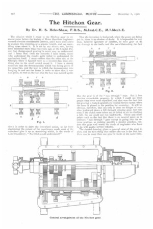
The allusion which I made to the Hitchon gear in ni■ recent paper before the Society of Motor Omnibus Engineer.; seemed to excite considerable interest, and I have been asked to explain this invention at a greater length, and say something more about it. It is not by any means new, having been exhibited more than two years ago at the Crystal Palace, but change-speed gearing is never easy to understand. and I fancy that, from the remarks I have heard, many who understood the results quite failed to understand the mechanism itself. I must confess that the other day at the Olympia Show it figured more as a mystery-box than anything else to the small crowd round it. I have a strong suspicion that the demonstration which was being given of its properties, and the way in which the demonstrator was banging in and out the levers in order to show that it was fool-proof, as well as the fact that the box was turned upside down in order to show the free-wheel action, so far from elucidating the nature of the contrivance made most of the onlookers give it up as something which, in the words of Lord Dundreary, " No fellah could understand !" Thar the invention is fool-proof, when the gears are being put in, there is no shadow of doubt. It is impossible for any man, however ignorant or careless, to miss gear or do any damage to the teeth, and this notwithstanding the fact that Ike gear is of the ." run through " type. But it has another remarkable property, by which I could see most people were even more mystified, and that was the fact that the gearing is locked against any reverse motion except when the lever is placed in the position for reversing. It will be obvious, therefore, that not only is there no danger of runninebackward down a hill through missing gear, but that even if the clutch were taken out or failed to net in climbing a hill, the car could not run backwards. These and other points such as the fact that there is no neutral space as in, ordinary " run through " gear except in going into the reverse position, so making possible a shorter gearbox, renders this gear well worth the study of engineers who have to do with public service vehicles. The shaded drawing gives a general view, of the gear hi plan, and the first thing that strikes the eye is the fact that there can be more than one gear in mesh at the same time_
This is also the peculiarity of gears of the always-in-mesh type, but there is this difference, that whereas in the latter kind of gear there are separate sliding keys or clutches to bring in action different changes of speeds, in the Hitchon gear a system of free-wheels (shown on the lower set of wheels) is used, which enables any wheel to overrun, and so the danger of breaking the teeth, when two gears are in mesh at the same time, is obviated.
In order to make the matter 'clear, I have prepared four diagrams, showing respectively Fig. i, the third or top; Fig. 2, the second or intermediate; Fig. 3, the first or low ; and Fig. 4, the reverse gears. In the first place it must be realised that the engine drives the shaft (E), the road wheels being connected in any suitable manner with the coupling which is shown in one piece with the wheel (A). E is squared, as shown, and on the squared portion slide the wheels (B, C, D), which are connected together, and are moved as one piece by a single lever. The wheels (b and c) have free-wheel connections with the way-shaft (SS), while the wheel (a) is keyed to it.
Looking now at Fig. 1, it is seen that the sliding piece (BCD) is moved as far to the left as possible, thus engaging the jaw clutch, and so causing the shaft (E) and coupling to turn together. Now, although the wheels (Bb and Cc) are in mesh with each other, the fact that the wheels (B and C) are respectively smaller than b and c causes the shaft
(SS) to overrun the free-wheel attachments of the latter, and their being in mesh presents no difficulty. This position gives direct, top, or third speed drive. Moving the piece (BCD) to the right (Fig. 2) disengages the clutch, and now, since the coupling must be turned, it is the larger wheel (C) which, through c, will do so, causing the wheel of the lower ratio pair (Bb) to overrun. This is the intermediate or second speed position. if now the piece (BCD) is moved a step further to the right, as shown in Fig. 3, the wheels (C and c) are disengaged, and Bb must now do the driving. This is the first or low speed position. Finally, the piece (BCD) can be moved still further to the right until D engages with the side pinion seen behind d, and B disengages with b. This side pinion is always in mesh with d, and, the drive being transmitted through it front D to d, a reverse motion is given to the wayshaft (SS), and so through A to the coupling (Fig. 4).
I have said that the piece (BCD) can be meshed with more than one wheel on the wayshaft (SS), as, owing to the freewheeling arrangement, the wayshaft overruns the slower drive. But, just as it is impossible to free-wheel on a bicycle that is being pulled backwards, so, if the car attempts to run backwards down a hill, the free-wheels (b, c) become fixed wheels, and—if the intermediate or high gear is in—the two shafts are locked together and no movement is possible.