


Useful Charts and Tables. No. I.
Page 2
Page 3
If you've noticed an error in this article please click here to report it so we can fix it.
By George Watson, Assoc.M.Inst.C.E.
Semi-Elliptical Springs for Motor Vehicles.
Most draughtsmen engaged in the design of motor vehicles have, from time to time, felt the need of tables and charts, prepared from reliable formula, for the calculation of such parts as semi-elliptical springs, etc. Were such tables at hand, a lot of time could be saved and more accurate results obtained than if it were necessary so often to repeat tedious mathematical calculations. They would be greatly appreciated by most designers, as they would allow them to devote more time to other considerations, and the final results would be more satisfactory to both employer and employed. Having felt the need of such tables, and realising the time they would save, the writer has, recently, prepared such as are almost daily needed by the motor-vehicle designer. The advantage of their use is apparent to all, if they are prepared
from reliable information. It need never be necessary to ge over the same ground twice, as all figures which are dependent upon each other can be reduced to a constant, or E curve, The writer will, in this article, confine himself to the con. sideration of plate springs, such as are used on motor vehicles. From careful consideration of the various formulr given in text and hand-books, and guided by several years experience in their design, the writer pins his faith to tta following formula, which is constantly used by more thin one of the well-known makers of motor-vehicle springs He has made careful tests, under the hydraulic press, o many springs made to this formula, and, in most cases, du actual tests agree, exactly, with the figures obtained by th(
formula, and, in no case, was there an error of more than 3 per cent_ I et The general design of a vehicle, usually, determines the length and breadth of a spring, and the load to be put upon it, leaving the thickness arid number of plates to be found by eaten la tion
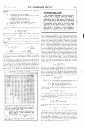
From the chart on page 286, these may be obtained-, without any other calculation than dividing the total toad in rwt. by the breadth of the spring in inches. As an example, let us suppose that a spring is required to carry a load of io cwt., and that the length of the spring is so inches, whilst the breadth of the plates is to be 21 inches. To find " t" and " n," first divide the load of lo cwt. by the breadth of 222 inches; lo ÷ 4 = 4 cwt. per inch breadth of the plate.
Now, from 50 on the left of the chart (representing the length), read across until the upward diagonal representing 4 cwt. is intersected : through the vertical line cutting this point, a series of downward diagonal lines pass, and these represent the thickness of the plate. Tracing to the right,. from any of these points of intersection, the number of plates. of that thickness will be found at the extreme right of the, chart. Any of the combinations on this vertical line would, give us a spring strong enough for the work, but they woulcd all vary in deflection under the same load. The final selection must, therefore, be determined by the deflection, as this. is often a matter of great importance. In many cases, the difference between loaded and unloaded condition is limited.
Reading down the vertical, we find that seven plates, each
inch thick, or 12 plates, each 3-16ths inch thick, may be used, whilst, if we read upwards, we find that 4 plates; each 5-16ths inch thick, may be used. This is, of course, impossible; so we should here use five plates, each 5-16ths inch thick, or four plates, each 5-56ths inch thick, and one plate
inch thick. In order to obtain the deflection we must use the formula
In order to simplify this formula, the annexed table of constants was prepared by the writer. It will be seen that this will meet all cases which are likely to come under the notice of the motor-vehicle designer, and that the ,tedious process of obtaining the " cubes " of the length and thickness is entirely eliminated, and the formula is reduced to a simple equation thus : Both the chart and the table are constructed from the formula given above, but a unit width of 1 inch has been taken, and a unit load of i cwt., as these values are of most use for the general run of motor vehicles. The writer has found this chart, and table, of very great service to him, as a time saver, and sincerely hopes that they may be of service to other designers, who are tired of wading through the old a5:d somewhat lengthy formula so many times.