


A New " Three-Tonner."
Page 4
Page 5
Page 6
If you've noticed an error in this article please click here to report it so we can fix it.
The Latest Model Produced by Halley's Industrial Motors, Limited, of Glasgow.
It k not often that: a young business concern does, during the course of a single year, design, manufacture, and demonstrate the capabilities of two new models, and receive for these vehicles a gold medal, a silver .medal, and a special award for having produced such extremely simple and reliable machines, vet such is the record of Halley's Industrial Motors, Limited, whose works are at Yoker, near Glasgow, and whose London office is at 25, Victoria Street, NVestminster, S.W., where Mr. D. Mc. N. Sharp superintends. the
c9mparty 's increasing business in thesouth. It will be remembered that the abovenamed rewards were obtained by the Flalley Company for two machines which it entered in, and ran during, the R.A.C. Trials of last autumn. The success which has attended those two models, and the demands which have been made by many users for a stilt larger machine, have led the company to design and produce a new model, the first of which a representative of this journal had an opportunity of examining in detail a few days ago, at the company's London garage.
The general features of this new machine are similar to those of the.,lighter vehicles which have already been 'described in " THE COMMERCIAL MOTOR " (see the issues for the 26th September and the 3rd October last). This new model is equipped with a 28-34h.p. engine, which has four separate water-jacketed cylinders, each of which is inches in diameter, and with pistons of a stroke of sl inches. The valves arc arranged on opposite sides of the engine, and the tappets are provided with means of adjustment to ensure that approximately the same lift can be given to the valves, although they and the faces of the cams may have become considerably worn by long usage.
Two sets of ignition are fitted, one of which is by means of a high-tension Bosch magneto, and the other by means of a high-tension, multi-cylinder coil and an accumulator ; the commutator is mounted on the top of a vertical shaft, situated at the forward end of the engine, and is driven from the inlet camshaft through skew gearing. On this vertical shaft a simple centrifugal governor is also mounted, and this automatically limits the speed of the engine to a maximum of 900 revolutions per minute, although, when occasion demands, the governor can be thrown out of action, and the speed of the engine accelerated to 1,200 revolutions per minute. For this purpose, an accelerator pedal is fitted, and this is interconnected with the hand-control lever to the throttle valve within the Brown-and-Barlow carburetter. The governor, commutater, and carburetter may clearly be seen in the left-hand illustration at the foot of this page, whilst, in the right-hand illustration, the centrifugal %%eater pump by which the water circulation is maintained can be seen. The pump is driven, by skew gearing, from the exhaust camshaft, through a short shaft which is provided with claw couplings that obviate the necessity for extremely careful alignment of the pump shalt with the pinion shaft from which it is driven,
In order to make easy the starting by hand of such a large engine, half-compression gear is fitted, and this is brought into operation by means of a small " pull-out " lever, situated at the base of the radiator in a position for it In be easily handled by the driver when starting up the engine.
All the bearings of the engine are lubricated on the force-feed principle, by means of an Albany gear-type of oil pump, which pump is bolted to the side of a deep sump in the lower part of the crank case and is driven by skew gearingfrom the exhaust camshaft. The oil from this pump is delivered through a relief-valve chamber to all the journal hearings of the engine, whence the oil is forced to the crank pins through channels in the crankshaft. A second pipe leads from the relief-valve chamber up to the dashboard, and terminates in a small pressure gauge, which indicates to the driver whether or not the pump is maintaining the desired pressure. Immediately a pre-determined pressure is exceeded, the relief valve is lifted against the pressure of the spring, and a part of the oil returns to the sump of the crank case without having passed through the bearings. The engine. is a very flexible one, and can be run at all intermediate speeds from 200 to 1,200 revolutions per minute.
The petrol tank, which has a capacity of rs gallons, is carried under the driver's seat, and the feed of the spirit to the carburetter is by gravity. The radiator is of the usual pattern employed by this company, and consists of vertically-arranged gilled tubes, whrise ends are secured in tube plates, which form part of the top and bottom
water vessels. Easily-removable covers permit the cleaning, when necessary, of all the tubes and other water passages in the radiator.
The exhaust gases are led into a very neatly-designed silencer, which is fixed transversely just over the back axle. The ends which close in the shell of this silencer are provided with incurved flanges, for the purpose of retaining the asbestos packing rings which are introduced before the ends arc placed on the cylindrical portion of the silencer ; having thus been loosely assembled, all the parts of the silencer are rigidly clamped together by means of a long bolt, which passes through the centre, and, by means of this bolt and two suspension brackets, the silencer is secured to the side members of the main frame. A series of baffle plates is threaded on to the centre bolt, before the ends of the silencer casing are placed in position to be clamped on to the shell.
The leather-faced cone clutch is of large diameter, and has a very wide face; the leather is riveted to the male cone in sections, underneath which a series of plate springs is introduced for the purpose of taking up the load gradually. Pressure between the friction surfaces is exerted by a helical spring, from which there is no damaging end thrust during the time that the clutch is engaged. The bridle by which the male cone is disengaged is provided with an efficient means of lubrication ; this is effected from a sight-feed lubricator on the dashboard, through a flexible metallic tube.
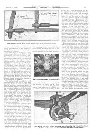
A universally-jointed propeller 'shaft transmits the drive from the clutch to the three-speed-and-reverse gearbox, a general-arrangement drawing of which we reproduce (page 528). This is of the company's usual always-in-mesh " type, and the teeth of the gear wheels are very wide. Any one pair of gears can he brought into operation by the engaging of the members of its claw coupling, and these are actuated front the driver's seat by means of a Daimlertype, gate-change, control lever. The pull from this lever is transmitted to the claw-clutch bridles within the gearbox by means of adjustable rods with neatly-designed universal joints, such as are seen in one of our illustrations. The hanging levers from the clawclutch bridle shafts are reduced in diameter, at their lower ends, and for a certain distance are left plain, as shown
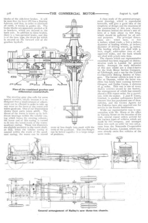
at A, whilst their extreme lower ends are screwed, as shown at B. Over these ends, special nuts (C) are fitted, and on these nuts there is a drilled boss to take the fork pivot pin (D). It will be seen that, after the special nuts -(C) are adjusted to the required positions on the hanging levers, they are prevented from slackening hack by means of the forks (E) on the ends of the rods. The three forward speeds provided for in this gearbox are : 4, io and 16 miles per hour, and the reverse speed is 41 miles an hour. The box is -provided Vtitil large and easily-removable inspection doors, which permit the ready adjustment of the dog clutches. The whole casing is suspended from the main frame members at three points. The final-drive bevels and the beveltype differential gear are both contained within the same casing as the changespeed mechanism. The side chain sprockets are mounted on the ends of the differential shaft, and these have twelve teeth to take Coventry chains of ti-inch pitch, through which the final drive to the back wheels is transmitted_ The construction of the bark axle calls for some comment, chiefly because the use of loose nuts to keep on the wheels has been avoided; the illustration of one end of the axle clearly shows how this has been carried into effect. A groove (L) is turned a short distance from each of the extreme ends of the axle, and this groove accommodates a split collar (M), which engages within a recess in the outer end of the drivingwheel hub, and limits the lateral [notion of the hub to about r-16th inch —the amount necessary for the efficient Lubrication of the thrust collars. The split collars are secured in place by the wheel cap, which in turn is locked to the hub by means of a spring ring. The hub and hub cap of the offside wheel is provided with left-hand threads, whilst those on the near-side wheel are provided with right-hand threads, in order that, when running forward, there is always a tendency for the cap to tighten up on the hubs, instead of slackening back. The journal parts of the back axle are provided with flats at the top, in order to assist the distribution of the lubricating medium, which is introduced through Lhe two grease cups shown in our illustration of the hub.
The illustration of one end of the back axle also shows the expanding brake blocks of the side-lever brakes. It will be seen that the lever (H) has a floating fulcrum, and that, in order to eliminate all rattle, it works in guides (J). The brake blocks are separately pivoted at K to brackets, which are secured to the back axle. In addition to these brakes, there is a foot-operated brake, and this is of the loco. type, the drum for which is secured on the forward end of the gearbox layshaft.
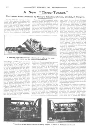
The steering gear also calls for some special mention, chiefly because it is so designed that a small amount of adjust-: ment can be effected in order to take tip any wear on the faces of the worrti and worm quadrant. One of our illustrations. shows these parts taken adrift. The. thrust of the worm is taken up by ballthrust bearings within the tubular casing which forms the steering column ; the lower end of this .casing is turned. to fit into the bored trunk of the wormquadrant casing. These two diameters are slightly eccentric to the worm shaft, so that, when the tubular casing is rotated within the trunk of the quadrant casing, the worm can be moved
more or less deeply into mesh with the teeth of the quadrant. The two flanges can be bolted together in a large range of positions. A close study of the general-arrangement drawing, which is reproduced herewith, will give a good idea of the simplicity of design and the stoutness of the construction of this new chassis ; the distance behind the driver's seat allows of a body about 13 feet long, which should be sufficient for all normal purposes. The principal dimen
sions are : wheel base, J2 feet 6 inches; wheel track, 4 feet 9 inches ; diameter of -leading wheels, 30 inches ; diameter of driving wheels, 34inches. The leading wheels are shod with 5_ inch, single, solid-rubber tires of any approved make, and the back wheels are shod with 5-inch twin tires.
The chassis which our representative examined has been engaged on demonstration work in London for several weeks. Amongst the early deliveries of this new Model are a char-a-hams for the Irish Motor Service Company, of Edinburgh, and a van for the United Co-Operative Baking Society of Glasgow. The former vehicle is now in service at Dunoon, whilst the latter machine has lately been running between Glasgow and Galles Camp, a distance of 33 miles. This van is one of many Halley vehicles owned by the Society, the management of which has recently placed a fifth repeat order, for a 3o-cwt. van, with the maker. J .and P. Coats, Limited, is another well-known Scotch concern that has purchased one of thes... vehicles, and the Crown Agents for the Colonies have also acquired one for service in the Straits Settlements.
While our representative was in conversation with Mr. Sharp at the office in Victoria Street on the occasion of his visit, several repeat orders arrived for the various types of vehicles which are made by this company, and amongst these was such an order for two 2oh.p. vans from the Newcastle Co-operative Wholesale Society, Limited, which concern already owns five vehicles of the same make.