


Patents Completed.
Page 18
If you've noticed an error in this article please click here to report it so we can fix it.
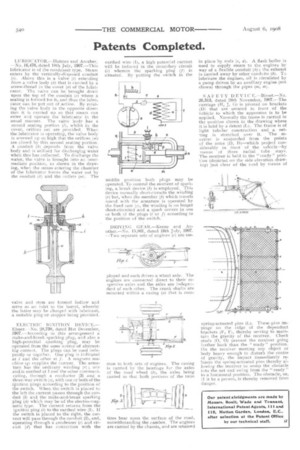
LOB RICA-FOR—Holmes and Another. —No. 16,476, dated 18th July, 1907.—This lubricator is of the condenser type. Steam enters by the vertically-disposed conduit (e). Above this is a valve (1) extending from a valve body (h) that is carried by a screw-thread in the cover (a) of the lubricator. The valve can be brought down upon the top of the conduit (e) where a seating is formed for it, and thus the lubri_ cator can be put out of action. By rotating the valve body in the opposite direction it is carried up so that steam can enter and operate the lubricator in the usual manner. The valve body has a second seating portion (/), whilst in the cover, orifices ml are provided. When the lubricator is operating, the valve body is screwed up so high that the orifices (m) are. dosed by this second seating portion. A conduit (t) depends from the valve body and is utilised for discharging water when this has collected. 'I'o discharge the water, the valve is brought into an intermediate position, as shown in the drawing, when the steam entering the chamber of the lubricator forces the water out by the conduit (k) and the outlets (m). The .valve and stem are formed hollow and serve as an inlet to the barrel, whereby the latter may be charged with lubricant, a suitable plug or stopper being provided.
ELECTRIC IGNITION DEVICE.— Ehnen—No. 28,738, dated 31st December, 1907.—According to this arrangement a make-and-break sparking plug, and also a high-potential sparking plug, may be operated from the same source of alternating current. The plugs cart be used indepently or together. One plug is indicated at i and the other at .1 A magneto machine g supplies the current. The armature has the ordinary winding (r) ; one end is earthed at land the other communicating, through a conductor (3) and a three-way switch (s), with one or both of the ignition plugs according to the position of the switch. When the switch is placed to the left the current passes through the conduit (5) and the make-and-break sparking plug (h) which may be of the electro-magnetic type. The current returns from the ignition plug (i) to the earthed wire (1). If the switch is placed to the right, the current will pass through the conduit (2), and, operating through a condenser (c) and circuit (d) that has connection with the
earthed wire (1), a high potential current will be induced in the secondary circuit (C) wherein the sparking plug (I) i5 situated. By putting the switch in the
middle position both plugs may be operated. To control the moment of sparking, a break device (17) is employed. This device normally short-circuits the winding (r) but, when the member (b) which travels round with the armature is operated by the fixed Cam (oh the winding is no longer short-circuited and a spark occurs in one or both of the plugs (i or jr) according to the position of the switch.
DRIVING GEAR,—Keene and Another—No, 15,861, dated 10th July, 1907, —Two separate sets of engines (c) are em ployed and each drives a wheel axle. The engines are connected direct to their respective axles and the axles are independent of each other. The crank shafts are mounted within a casing (a) that is corn mon to both sets of engines. The casing is carried by the bearings for the axles of the road wheel (II, the axles being canted so that both portions of the twin tires bear upon the surface of the road, notwithstanding the camber. The engines are carried by the chassis, arid are retained in place by rods (e, cl). A flash boiler is used to supply steam to the engines by way of a flexible conduit (h); the exhaust is carried away by other conduits (k). To lubricate the engines, oil is circulated by a pump driven by an auxiliary engine (not shown) through the pipes (ni, sn).
SAFETY DEVICE.—Bisset.—No. 26,313, dated 28th November, 1907.—The carriage (H, J, G) is pivoted on brackets (D) that are secured in front of the vehicle to which the apparatus is to be applied. Normally the frame is carried in the position shown in the drawing where it is held by a detent The frame is of light tubular construction and a netting is stretched over it. The receiver is suspended from the points of the arms (D, D)—which project considerably in front of the vehicle—by means of three radial tube stays. The receiver is held in the " ready" position (depicted on the side elevation drawing) just clear of the road by means of spring-actuated pins (L). These ,pins impinge on the ridge of the dependent brackets (F, F), thereby serving to maintain the gravity of the receiver. Check studs (0, 0) prevent the receiver going further back titan the " ready" position. On the receiver Meeting any object or body heavy enough to disturb the centre of gravity, the 'impact immediately releases the spring-actuated pins thereby allowing the receiver to scoop the obstacle into the net and swing from the " ready " to a horizontal position. The obstacle, or, if it be a person, is thereby removed from danger.