


An Excess fuel Device
Page 48
If you've noticed an error in this article please click here to report it so we can fix it.
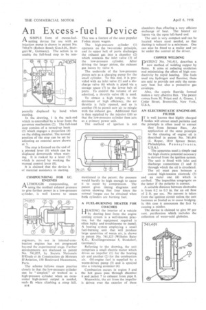
A SIMPLE form of excess-fuelI-I setting device for use with an injection pump is shown in patent No. 740,674 (Robert Bosch G.m.b.H., Stuttgart-W., Germany). The action is to enable the full-load stop to be tern
porarily displaced by hand when starting.
In the drawing, 1 is the rack-rod which is controlled by a lever from the governor mechanism (2). The full-load stop consists of a turned-up hook (3) which engages a projection (4) on the sliding member. The normal position of the stop can be set by adjusting an external screw shown at 5.
The stop is formed on the end of a pivoted lever (6) which can be displaced downwards when starting. It is rocked by a lever (7) which is moved by working the manual control lever (8).
It is claimed that the device is of material assistance in starting.
COMPOUNDING FOR LC. ENGINES
A LTHOUGH compounding, or using the residual exhaust pressure to give further power in a low-pressure cylinder, is well known to steam
engineers, its use in internal-combustion engines has not progressed beyond the experimental stage. Further developments are disclosed in patent No. 741,855, by Societe Nationale D'Etucle et de Construction de Moteurs D'Aviation, 150 Boulevard Haussmann, Paris.
The scheme follows steam practice closely in that the low-pressure cylinder can be " simpled," or worked as a high-pressure cylinder when an occasional high-power output is needed, such ts when climbing a steep hill.
)314 This was a feature of the once popular Foden steam wagon.
The high-pressure cylinder (1) operates on the two-stroke principle, and its upper belt of ports discharges the exhaust gas into a chamber (2) which contains the inlet valve (3) of the low-pressure cylinder. After driving the larger piston, the exhaust gas leaves by valve 4.
The underside of the low-pressure piston acts as a charging pump for the small cylinder. To this end, it is provided with an inlet valve (5) and a discharge valve (6) which is piped via a storage space (7) to the lower belt of ports. To control the volume of air admitted, a throttle valve (8) is used.
To obtain a high torque, to the detriment of high efficiency, the air throttle is fully opened, and so is another (9) to permit new air to mingle with the exhaust gas. Additional fuel is then supplied by the injector (10) so that the low-pressure cylinder then acts as a primary power unit.
The method of ignition is not
mentioned in the patent; the pressure would hardly be high enough to cause it to occur by compression. The patent gives timing diagrams and curves showing that four times the normal torque can be obtained when both cylinders are burning fuel.
A FUEL-BURNING HEATER FOR COACHES
LJEATING the interior of a vehicle
I by ducting heat from the engine cooling system is a well-known practice, but the equipment required is often bulky and troublesome to install. A heating system employing a small fuel-burning unit that will produce large quantities of warm air, is shown in patent No. 741,125 (Wilhelm Baler K.G., Kraillingerstrasse 5, Stockdorf, Germany).
Referring to the drawing, the unit comprises a small electric motor which drives an impeller (1) for the heating air and another (2) for the combustion air. Oil-engine fuel is supplied by a worm-driven pump (3) and is sprayed into a rotating atomizer (4).
Combustion occurs in region 5 and the hot gases pass through chamber 6and jacket 7 to exhaust from pipe 8.
Meanwhile, the air from the impeller is driven over the exterior of these chambers thus effecting a very efficient exchange of heat. The heated air leaves via the open left-hand end.
The unit is very compact and can be located where most needed, so that ducting is reduced to a minimum. One can also be fitted to a trailer and yet be under the control of the driver.
COPPER WELDING PATENT No. 741,411, describes a new method of welding copper by flame. It aims at reducing oxidation and minimizing the effect of high conductivity by rapid heating. The fuels used are hydrogen and fluorine; these are said to provide not only the necessary heat but also a protective gas envelope.
Also, the cupric fluoride formed makes a very effective flux. The patent comes from H. Priest and A. Grasse, 1 Cedar Street, Bronxville, New York, U.S. A.
AN ELECTROSTATIC ENGINE-OIL FILTER IT is well known that highly charged I bodies will attract small particles and the principle is often used to extract dust from furnace flues. An application of the same principle to the cleaning of engine oil is described in patent No. 741,491 (I. Roper, 1810 Spruce Street, Philadelphia, Pennsylvania,
U.S.A.). • The apparatus used is simple and the high electric potential necessary is derived from the ignition system. The unit is fitted with inlet and discharge connections (1 and 2) through which the oil is circulated. The oil must pass between a central high-tension electrode (3) and an outer one (4) which is earthed. The impurities congregate on the latter if the polarity is correct.
A suitable distance between electrodes is from 0.2 to 0.3 in. for an oil flow of 2 ft. per sec. No current is taken from the ignition circuit unless the unit becomes so fouled as to cause bridging. In this case it announces the fact by causing a misfire.
The device is claimed to give 99 per cent, purification which includes the collection of water-acid globules.