


Patents Completed.
Page 20
If you've noticed an error in this article please click here to report it so we can fix it.
Complete specifications of the following patents will be sent to any address in the United Kingdom upon receipt of eightpence per copy at the Sale Branch, Patent Office, Holborn, W.C.
VALVE MOUNTINGS. — Daimler Motoren Gesellschait.—No. 6,278, of 1910, dated under Convention 15th March, 1909.—This invention provides for the use, in internal-combustion-engine cylinders, of valves arranged in the cylinder head, when the sum of the diameters of the two valves is greater than the diameter of the cylinder. A slight enlargement is made in the combustion chamber, and the guide bushes for the valve spindle are fitted into sockets having an internal diameter which is greater than the diameter of the valve spindles, by an amount. which is at least double the extent to which the edge of the valve disc projects beyond the cylinder bore. The two illustrations herewith show the valves in place and the valve being introduced. An alternative construction, in which an eccentrically-bored bush is used, is also described and illustrated.
SILENT CHAINS.—Allingham.—No. 9,295, dated 16th April, 1910.—The invention described in this specification relates to driving chains of the kind in which cylinder pins are used to connect the links, these pins being surrounded by bushes in order to decrease the wear on the links. According to this invention, circular bushes are driven into the holes in each link for the joint pins, hut each bush is provided with a segmental extension on its working side, an that this part of the bush is longer than the thick. ness of the link, and on the opposite or idle side of the bush its length is made correspo idingly less than the th ckness of the li ik. When, therefore, the links are aseembled to form a chain, the bushes are arranged so that the extended portion of one bush is adjacent to the diminished portion of the next bush, and the total bearing surface between the bushes and the joint pins is the sum of the extended pertions of the bushes of alternate lengths. CARBURETTER. — Johnson. — No. 21,741, dated 19th September, 1910.— The carburettor described in this specification is arranged to do away with the necessity of heating the combustible mixture by the exhaust or other inconvenient or expensive methods. The heating of the carburetter is effected, according to this invention, by arranging it adjacent to and integral with the cylinders, so that it is almost entirely surrounded by the water jacket ; in this way, the whole of the carburetter is maintained at a uniform temperature approximate to that of the cylinders, and the channels for distributing the mixture are very short. In the form illustrated two nozzles are pro
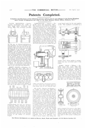
OIL PUNIP.—Sheppee and Shippey.— No. 15.098, dated 30th May, 1910.—The pump described in this specification is on which is specially applicable for the use of oil or viscous liquids. In the bottom if an oil tank, two pump barrels are provided, communicating with the tank by holes formed in the skin for inlets ; these are closed by valves which are held up against their own weight by a camactuated lever. The plungers are formed of solid rods and are arranged in couples, being actuated by earns on the camshaft. A rocking crosshead is pivoted between the two plungers, so that the positive forward movement of the one acts through the crosshead and causes the return stroke of the other. The inlet valve falls by its own weight. as soon as the lever is released by its cam, and, since the suction inlet has been reduced in length to a minimum, there is no difficulty, -even with a viscous liquid, when filling the
pomp barrel ready for the next positive stroke. The camshaft is actuated by a ratchet wheel, whose ratchet is reciprocated from any convenient part of the engine.
WORM GEAR. — Hillman. — No. 9,725, dated 21st April, 1910.—The object of this invention is to reduce the friction in worm gearing. Instead of forming ordinary threads on the worm and wheel, grooves are cut. in each of them, and about three rollers or balls are arranged in each groove in the worm wheel ; they are held in place by a ring which is fixed round the central plane of the wheel, an opening in this ring permits the worm to operate on the balls
and to transmit the power to the wheel. In doing this the halls are displaced to the side of the wheel and are brought back by suitable guides to the centre and passed round the wheel, coming into action again in their proper working position.