


The ATLANTEAN Gets Down to Business
Page 44
Page 45
Page 46
If you've noticed an error in this article please click here to report it so we can fix it.
• New Leyland has Separate . Chassis and Beam Ax/es: Simplified Design Gives
• Greater Choice of Body Layouts : Low-height Frame for Easy Loading and Low Overall Body Height.
GREAT interest has been stimiilated among fleet operators by the various designs of Leyland Atlantean rear-engined double-decker which have been exhibitedat Earls Court and demonstrated in fleet service over the past four years. This has encouraged Leyland Motors, Ltd., to complete a design giving all the advantages of the earlier integral versions, but employing a chassis frame • and more simple mechanical components with the object of making the price competitive with that of conventional double-decker bus chassis.
Because of its conventional approach the latest Atlantean • is perhaps even more outstanding than the previous design, particularly as . normal beam axles are used at front and rear without detracting from the lowplatform front entrance which was one of the important features of the 1956 version. It will be possible on the new chassis to build a • double-deck body within an unladen vehicle height of 13 ft. 4 in. without recourse to a sidegangway upper-deck layout except for a short section at the rear.
Bodybuilders will no banger be restricted in the type of body that can be offered with the Atlantean, this having been one of the shortcomings of the fully stressed body-chassis construction as originally envisaged. Thus, operators will be free to choose their own bodybuilders and to specify their own interior layouts.
A criticism that was sometimes levelled at•the original Atlantean design was that because the power unit was carried across the rear Of the body, within the main body shell, there was a pronounced tendency for noise and vibration to be transmitted throughout the whole of the body.
A further possible disadvantage of the 1956 design was that in the event of a rear-end collision not only might the engine be damaged, but the complete body sub-frame and superstructure would also need repairing: no simple matter with a fully integral design.
To combat these weaknesses the new vehicle has the engine mounted on a robust, easily detachable sub-frame, so that, in conjunction with the gearbox, bevel box and cooling system, it forms a complete power pack. This is enclosed in a plastics cowl which is intended to protrude from the rear of the lower saloon (the upper saloon being cantilevered over it). In this Way the engine is insulated from the passenger compartment and becomes more accessible for routine maintenance or complete removal.
The use of a separate chassis frame and rigid rear-end assembly ensures extra strength to withstand collisions from behind. Any damage should in most cases be no greater than that caused to a normal front-engined double-decker.
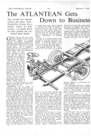
The standard Atlantean has a wheelbase of 16 ft. 3 in. and a rear overhang of 6 ft. 81 in., the front overhang being only in. longer less towing eyes. The frame side members are *-in.-thick pressings, having 3-in, flanges and a maximum depth of 8 in. They are swept up sharply over the rear axle, the difference in height of the top flanges being 16 in., whilst over the front axle the frame rises 3.6 in. above the main inter-axle height.
Forward of the front axle the near-side frame member is dropped by 6.85 in., whilst the off-side member remains level with the too of the axle hump to Support the driving platform.
Behind the rear axle there is a robust arrangement of four bracing members, which tie up the back end of the frame, support the power pack, arid 'reduce the mid-chassis bending moments. Consequently, relatively light main . members between the axles can be used.
Except at the rear-spring rear hanger brackets, tubular cross-members are bolted to the frame at the spring anchor age points, In addition, there are thre channel-section members, also bolted.
In line with each of these cross members there are bolted outriggers, thi upper flanges of which are generally leve with the upper flanges of the side mem bers. The exception is the near-side iron outrigger, the outer end of which i
dropped slightly to accommodate the loading platform.
The power-pack sub-frame is welded Its rear end incorporates a heavy channelsection member, Curved at its outer ends to act as a main bumper. The power pack is secured to the main frame assembly by 14 bolts.
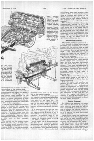
A net power output of 125 b.h.p. al 1,800 r.p.m. is given by the Leyland 0.60C 9.8-litre six-cylindered direct-injection oil engine. Basically this unit is identical with the 0.600 engine used in other Leyland goods and passenger chassis; but there are a few detail modifications. Foi instance, the fuel-injection pump has a hydraulic governor, this having been used to ensure constant idling under all temperature conditions and so redue: vibration.
An innOvation is the use of a paperelement air filter, which, in addition tc being smaller and lighter than the type of oil-bath cleaner necessary with this size of engine, is claimed to be more efficieni and to have a longer life between maintenance pericids. The filter is at least at efficient a sound deadener as an oil-bath unit and, as employed in the Atlantean, is
fed through a cold-air intake ducted from a point ahead of the radiator block.
Fuel is filtered through a sediment bowl mounted on the sub-frame. with which is incorporated a cut-off tap, and twin paper-element filters mounted on the crankcase immediately below the injection pump. A Glacier centrifugal oil filter ensures maximum cleanliness in lubrication. An external engine-stop control will be fitted by the bodybuilder.
A Leyland 16i-in.-diameter centrifugal clutch is standard, this having been adopted to give greater efficiency, and therefore better fuel economy, than is obtainable with a conventional fluid coupling. The drive passes from this clutch to a Pneumo-Cyclic four-speed clectro-pneumatically operated direct acting epicyclic gearbox, which is offered in either semior fully automatic versions.
The gearbox has the standard ratios, which are 4.28, 2.43, 1.54 and 1 to 1 forward, with a reverse ratio of 5.97 to I. Gear changing is controlled by a small switch on the left of the steering column, which operates the solenoid-controlled pneumatic valve block on the forward side of the engine crankcase.
Mounted in unit with the engine-gearbox assembly, but having an independent lubrication system from either of the other units, is a 48° bevel box. This incorporates helical reduction gearing, and it is this gearing which is changed to suit the requirements of any particular operator in respect of a specific final-drive ratio.
It is much cheaper to offer an alternative set of helical gears for the bevel box than to provide a variety of sets of crown wheels and pinions. In the Leyland final-drive arrangement there is one standard rear-axle ratio of 3.083 to 1, but a choice of final-drive ratios of 6.074, 5.334, 4.702 and 4.15 to 1.
At the output end of the bevel box are the drive for an electrically operated speedometer and a flange on which may be mounted a generator for the control of the Pneumo-Cyclic gearbox in its fully automatic version. The Propeller-shaft output-flange has a single V-pulley, which is used to drive an automatic lubricator, fitted as standard and feeding all the chassis points through nylon piping and leaving only the three greasing points on the propeller shaft requiring periodic attention.
The radiator, mounted above the Pneumo-Cyclic gearbox, isof a new integral limited-loss deSign in which any water driven out of the header tank by expansion passes to a reservoir in front of, but integral with, the header tank. From there it is drawn again, as the water temperature in the main radiator block drops. This ensures that none of the coolant is lost no matter what the operating conditions may be.
Pressurized Radiator
The cooling system is pressurized to 4 p.s.i. Behind the block there is a cast six-bladed fan supported in bearings integral with the cowl to allow a blade clearance of less than 0.012 in. to ensure the maximum flow of air through the block. This high-efficiency layout reduces the height of the radiator, so keeping the overall size of the power pack down to minimum.
Air 113 drawn through the radiator from the right-hand side of the vehicle, and the plastics engine cowl incorporates the upper half of a metal duct which mates with the lower half carried on the radiator. Thus, when the engine cowl is closed, all the air drawn in passes through the radiator. In this way the re-circulation of hot air within the cowl is prevented, which in turn helps to pressurize the engine compartment and so keep out dirt.
The fan has a twin V-belt drive, the driving pulley being at the end of a jointed shaft which is driven from the engine timing case.
Both the engine and gearbox are mounted at four points on their subframe. There are two sandwich-type rubbers in compression and shear at the timing-case end and two inclined conical rubber mountings close to the clutch housing. This arrangement is similar to that employed on the 1956 bus, but because the engine will always be removed as part of the complete power pack, there will seldom be need to disturb the four rubber mountings.
Simple Removal
To withdraw the assembly it is necessary only to disconnect the propeller shaft, electrical leads, and fuel and air lines—all of which are easily accessible— and to unfasten the rod-type accelerator linkage, which is automatically tensioned so as to take up free play which might occur in operation.
As the cooling system also is withdrawn with the power pack, the complete engine unit can be run when removed from the chassis merely by connecting up the twin silencers and an external fuel system.
Big fleet operators will be able to keep spare power packs ready for instant replacement, and a used assembly can be reconditioned at leisure and all final settings and adjustments made before its
replacement into a chassis. The dry weight of the power pack, complete with its sub-frame, is 1 ton 91 cwt.
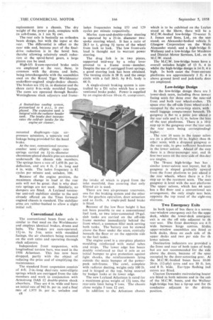
The rear axle is basically an orthodox beam design, but with the input at the rear. The differential is offset to the near side and, because part of the finaldrive reduction is in the bevel box, thereby allowing relatively small reduction at the spiral-bevel gears, a large pinion can be used.
High-lift S-cam-operated brake units are employed at the rear,' these, in common with the drums and hubs, being interchangeable with the assemblies used on the Royal Tiger Worldmaster underfloor-engined single-decker chassis. The brakes are 151 in. in diameter and the shoes carry 8-in.-wide moulded facings. The earns are operated through BendixWestinghouse slack adjusters and frame mounted diaphragm type airpressure actuators, a separate rod linkage being provided for the hand brake.
At the rear, conventional reversecamber semi elliptic single rate springs carried on 11-in.-diameter chromium-plated shackle pins are mounted underneath the chassis side members. The springs have a rate of 1,450 lb. per in. deflection, and are 4 ft. 2 in. long and 4 in. wide. The sladen frequency is 82 cycles per minute and, unladen, 106.
Because of the engine position, the maximum change in load at the rear axle will not be great: that is why dualrate springs are not used. Similarly, no dampers are fitted. A Leyland torsionbar anti-roll stabilizer similar to the unit already offered on the Titan forwardengined chassis is standard. The stabilizer arms are rubber-bushed to allow a slight initial roll:
Conventional Axle
The conventional beam front axle is similar to that used on the Worldmaster and employs identical brakes, drums and hubs. The brakes are cam-operated, 151-in. by 5-in. units with moulded facings, the air chambers being mounted on the stub axles and operating through slack adjusters.
Independent front suspension, with longitudinal torsion bars, was used in the 1956 Atlantean. This has now been dropped, partly with the object of reducing the price and of simplifying the maintenance.
The standard front suspension consists of 4-ft. 2-in.-long dual-rate semi-elliptic springs which are outriggcd from the side members and work in conjunction with Armstrong DAS 12 double-piston shock absorbers. They are 4 in. wide and have an initial rate of 942 lb. per in. and a final rate of 1,975 lb. per in., unladen and c8 laden frequencies being 153 and 129 cycles per minute respectively.
Marles cam-and-double-roller steering is operated by a 21-in, diameter twospoke steering wheel. It has a ratio of 28.5 to 1, giving 51 turns of the wheel from lock to lock. The low front-axle load is thought not to warrant power steering.
The drag link is in two pieces, supported mid-way by a relay lever pivoted to a frame cross member, Despite the use of outrigged front springs, a good steering lock has been obtained. The turning circle is 58 ft. and the swept circle with a full 30-ft. by 8-ft. body is 66 ft.
A single-circuit braking system is controlled by a D1 valve which has a conventional brake pedal. Power is supplied by an engine-driven 10-cu.-ft. compressor, the intake of which is piped from the inlet manifold, thus ensuring that only filtered air is used.
There are two air-pressure reservoirs, one for the braking system and the other for the gearbox operation, door actuation and so forth. A single-pull hand brake is fitted.
Because of the low floor height it has not been possible to use a conventional fuel tank, so two inter-connected 19-gal. slab tanks are carried on the off-side frame member immediately behind the front wheel, a common filler neck serving both tanks. The 'battery can be stowed above the floor under the scats, centrally beneath the floor or on the opposite side to the fuel tanks.
The engine cowl is a one-piece plastics moulding reinforced with metal tubes and strips. The lower edge has becen doubly reinforced so that it acts as an initial bumper to give protection against light shocks, the reinforcements lying outside the main bumper of the powerpack sub-frame. The cowl, complete with radiator ducting, weighs only 100 lb. and is hinged at the top, being secured by budget locks at its lower edge.
The new Leyland Atlantean is rated for a maximum gross weight of 131 tons, the rear-axle limit being 9 tons. The chassis alone weighs 5 tons 12 cwt.
In addition to the Atlantean chassis which is to be exhibited on the LeyIan stand at the Show, there will be a M.C.W.-bodied low-bridge 73-seater fc J. James and Sons, Ltd., on the sarn stand; an Alexander-bodied vehicle fc Glasgow Corporation on the Walt Alexander stand; and a high-bridge Cc Wallasey and a low-bridge for Maidston and District Motor Services, Ltd., on th M.G.W. stand.
The M.C.W. low-bridge buses have a overall unladen height of 13 ft. 4 in whilst the high-bridge design is 14 ft. 4 ir high. In both cases the front-cutranc platforms are approximately 1 ft. 4 it above ground level and jack-knife door are employed.
Low-bridge Design
In the low-bridge design there are 3 lower-deck seats, including three inward facing seats for three over the near-sid front and both rear wheel-arches. Th space over the off-side front wheel-arch i occupied by the seven-step stairs, with small luggage compartment beneath. Th gangway is flat to a point just ahead o the rear axle and is 31 in. below the leve ofthe seat platforms. There is a 10-ir step up in the gangway over the rear axlc the rear seats being correSpondingl higher. -' • The rear 16 seats in the upper satooi are on a platform 10 in. higher than th other seats, with a dropped gangway oi the near side, to give sufficient headroon in the lower saloon. Ahead pf the step there is a three-passenger seat, and th first two seats ori the near side of this decl are singles.
The 78-seat high-bridge bus has . similar lower-saloon seat layout, but th gangway is sloped gradually upward from the front platform to just ahead o the rear wheels, where there is a 5-in step up to the rearmost seats. The mail gangway is level with the seat platforms The upper saloon, which has 44 seats has a flat floor and a conventional sea arrangement, the only single seat bein; opposite the top tread of the eight-stet staircase.
Two Emergency Exits
In both types of bus there is a norma rear-window emergency exit for the uppe deck, .whilst the lower-deck emergenc: exit is on the off side adjacent to tb. rear seat. The front doorways are 4ft wide between hinge centres. Slidin; upper-window assemblies are fitted oi both decks. three on each side of th. upper decks and two per side for th, lower saloon.
Destination indicators are provided a the front and rear of both types of body but are not recommended for the side above the doors, because of the spac, occupied by the door-actuating gear. Al the M.C.W.-bodied buses have 10.00. 20-in. (12-ply) tyres and are 30 ft. lon; and 8 ft. wide. Ear-type flashing indi cators are fitted.
Clayton Dewandre recirculating heater are fitted in both saloons and in the cab of the M.C.W. buses, and the Wallase: high-bridge bus has a tip-up seat for ib. conductor adjacent to the drivin; position.