


AN AUTOMATIC CHANGE-SPEED GEAR.
Page 30
If you've noticed an error in this article please click here to report it so we can fix it.
A Résumé of Recently Published Patents.
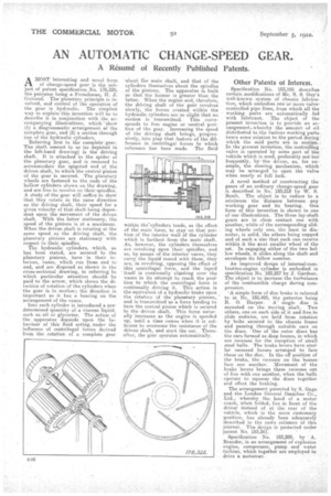
AMOST interesting and novel form of change-speed gear is the subject of patent specification No. 176,325, the patentee being a Frenchman, II. J. einiraud: The planetary principle is involved, and control of the operation of the gear is hydraulic. The simplest way to explain this invention will be to describe it in conjunction with the accompanying illustrations, which 'show (1) a diagrammatic arrangement of the complete gear, and (2) a section through 'One of the hydraulic cylinders.
Referring first to the complete gear. The shaft tiearest to us (as depicted in the left-hand drawing) is the driving shaft. It is attached to the spider of the planetary gear, and is recessed to accommodate the spigoted end of the driven shaft, to which the central pinion of the gear is secured. The planetary wheels are fastened to the ends of the hollow cylinders shown on the drawing, and are free to revolve on their-spindles. A study of the gear will suffice to show that they rotate in the same direction as the driving shaft, their speed for a given velocity of that shaft being dependent upon the movement of the driven shaft. With the latter stationary, the speed of the pinions is at a maximum. When the driven shaft is rotating at the same speed as the driving shaft, the planetary pinions are stationary with respect to their spindles.
The hydraulic cylinders, which, as has been stated, are secured to the planetary pinions, have in their interiors, vanes, which run from end to end, and are disposed as shown in the cross-sectional drawing, in referring to which particular attention shouldbe paid to the arrow, which shows the direction of rotation of the cylinders when the gear is in motion; the direction is important as it has a bearing on the arrangement of the vanes.
Into each cylinder is introduced a predetermined quantity of a viscous liquid, such as oil or glycerine. The action of the apparatus depends upon the behaviour of this fluid acting, under the influence of centrifugal forces derived from the rotation of a complete gear
'about the main shaft, and that of the cylinders themselves about the spindles of the pinions. The apparatus is.built so that the former is greater than the latter. When the engine and, therefore, the driving shaft of the gear revolves slowly, the forces created within the hydraulic cylinders are so slight that no motion is transmitted. This corresponds to free engine or neutral position of the gear. Increasing the speed of the driving shaft brings, progressively, into play that feature of the difference in centrifugal force-s to which reference has been made. -The fluid within the-cylinders tends, as the effect of the main force, to stay on that portion of the interior wall of the cylinder which is farthest from the main shaft. As, however, the cylinders themselves are revolving upon their spindles, and as, by means of the interior vanes, they carry the liquid round with them, they are, in revolving, opposing the effect of this centrifugal force, and the liquid itself is continually climbing over the vanes in its attempt to reach the position to which the centrifugal force is continually driving it. This action is the equivalent of a hydraulic brake upon the rotation of the planetary pinions, and is transmitted as a force tending to turn the central pinion which is secured to the driven shaft. This force naturally increases as the engine is speeded up, until a time comes when it is sufficient to overcome the resistance of the driven shaft, and start the car. Thereafter, the gear operates automatically.
Other Patents of Interest.
Specification No. 183,155 describes certain modifications of Mr. S. S. Guy's well-known system of chassis lubrica tion, which embodies one or more valvecontrolled pipe lines, from which all the working parts are automatically fed with lubricant. The object of the present invention is to provide an ar rangement, whereby the amount of oil distributed to the various working parts bears some relation to the period during which the said parts are in moqon. In the present invention, the controlling valve is operated by some part of the
vehicle which is used, preferably not too frequently, bythe driver, as, for example, the steering mechanism, which may be arranged to open the valve when nearly at full lock.
A novel method of constructing the gears of an ordinary change-speed gear is described in No. 183,216 by W. S.
Bonk. The object is to reduce to a minimum the distance between any working gear and its bearing. One form of this invention is shown in one of our illustrations. The three lay-shaft gears are in close contact one with another, while of the corresponding sliding wheels only one, the least in dia meter, is solid, the ethers being cupped and of such a size that each can receive within it the next smaller wheel of the set. In engaging either of the two hollow wheels, it slides along the shaft and envelopes its fellow member.
An improved design of internal-combustion-engine cylinder is embodied in specification No. 183,257 by ,T. Gardner. The object is to increase the turbulence of the combustible charge during compression.
'A simple form of disc brake is referred to in No. 183,405, the patentee being
R. 0. Harper. A. single disc is
mounted on the moving shaft. Two others, one on each side of it and free to slide endwise, are held from rotation by bolts secured to the chassis frame and passing through suitable ears on the discs. One of the outer discs has the ears formed as deep bosses, in which are recesses for the reception of small steel balls. The brake levers have similar recessed bosses arranged to face those on the disc. In the off position of the brake, the recesses on the bosses • face one another. Movement of the brake levers brings these recesses out of line with one another, when the balls operate to squeeze the discs together and effect the braking.
The arrangement patented by S. Gage arid the London General Omnibus Co., Ltd., whereby the hood of a motor coach, when folded, lies in front of the driver instead of at the rear of the
vehicle, which is the more customary position, has already been adequately described in the news columns of this journal. The design is-protected under patent No. 183,341.
Specification No. 183,288, by A. Brander, is an arrangement of explosion engine, compressor, pump and water turbine, which together are employed to drive a motorcar.