


A New Two-stroke Oil Engine
Page 68
If you've noticed an error in this article please click here to report it so we can fix it.
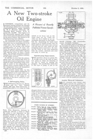
A Resume' of Recently Published Patent Specifications LIGHTNESS, compactness and decreased bearing pressure are amongst the advantages claimed for a two-stroke compression-ignition engine described by W. S. Renwick, A.M.I.A.E-, 67, Stemdale Road, London, W.I4, in patent No. 414,986. This engine is of the horizontally opposed type, having one or more pairs of cylinders according to the power desired, that shown in the drawing having four cylinders.
The interesting feature of this engine is the crankshaft and piston assembly. The piston has no connecting rod of the usual type, but is bolted rigidly to a T-shaped rod (2) having a fiat sliding bearing-surface (1) at its inner end. From the opposite piston a similar rod projects, the pair being bolted together with spacing collars to form a double slide. The crankpin (3) carries a square bearing block which oscillates vertically as the engine revolves.
It will thus be seen that the pistons, piston rods, and bearing slide move as one in pure reciprocating motion, which results in their momentum being available to assist in the colnpression, as distinct from a normal engine in which the compression forces are transmitted through the big-end bearings.
The inventor claims that, by this method, a much lighter construction of the crankshaft can be used, with a consequent decrease in weight and cost. A further feature of this engine is the operation of the sleeve valves, by a system of levers.
A Self-energizing Brake.
THE well-known concerti of J. Brockhouse and Co., Ltd., Victoria Works, Hill Top, West Bromwich, in conjunction with A. T. C. Dear, 6, Coles
Lane, West Bromwich, discloses, in patent No. 415,121, a brake in which the action is not dependent on the physical strength of the driver. The necessary power is derived from the rotation of the drum, and is applied in the following manner : —The brake band is in one piece and encircles almost the entire inner periphery of the drum. A fixed stud (1) supports the band, at the same time allowing a certain amount of peripheral movement due to the slot (2). A long link (3), operated by the outside lever, is a t EDO tached at its lower end to the brake band eye (4), whilst the other eye (6) is linked to an approximate mid-point on the longer link (3). Expanding the brake band causes it to be carried around with the drum until one end comes into contact with the stop (5), after which the selfenergizing action commences. By making the width of this stop adjustable from the outside, slackness and wear can easily be taken up.
Injection-pump Improvements.
THE invention shown in patent No. 414,983 refers to the type of injec
tion pump which the metering of the fuel is varied by turning the plungers. The specification states that in this type of pump, if one of the plungers should jam in its cylinder, the whole metering system becomes locked, owing to the fact that a multi-cylinder pump has a common control rack-rod. To overcome this defect is the object of the patentees, Simms Motor Units, Ltd„ Grease Street, London, W.1, and Rudolf l'Orange, 130, Cannstatlerstrasse, Stuttgart, Germany.
One of several ways of carrying out the invention is shown in the drawing. The rotating control sleeve (6) is provided with two diametrical slots (5), which normally would engage with some form of cross-pin on the plunger. In this invention, however, a second sleeve (3), having projecting lugs (2), engages with the slots (5), and lifts the plunger through a cross-pin (1). This pin has knife-edges which rest in notches on the top of the sleeve (3) and are held there by the smaller spring (4).
During normal operation the plunger, the sleeve (3), and the spring (4) all move as one, but should the plunger jam (being raised by the cam and not returnifig) the spring (4) would be compressed by the more powerful outside spring and cause the cross-pin to be lifted out of its notch. This would leave the control 4leeve (6) free to tun in unison with the unaffected cylinders.
Another Heavy-oil Carburetter.
Ik RANY inventors have turned their 0.VIthoughts towards the possibility of using oil fuel for spark-ignited engines, several patents of late being directed towards this end. Patent No. 415,024 discloses a design of carburetter in which the fuel is first mixed with a small amount of air and converted into a rich spray, after which it is drawn into a choke tube and mixed with the correct ratio of air for combustion. The patentee is E. Mathieu, 25bis rue du Chateau, Neuilly-sur-Seine, France,
The drawing shows a section of the nucleus of the device, which comprises a circular chamber into which the fuel is sprayed under pressure from a nozzle. The direction of the jet is tangential to the chamber, as arc also the air jets, so that a high degree of rotation of the mixture is obtained. By drawing off the mixture from the centre of the chamber, the inventor claims that only the finest atomized portion is abstracted, the heavier droplets being flung on to the walls, whence they drain back to the supply. A feature of the invention is the continuous 'atomization of an excess quantity of fuel, so that the proportions of the ultimate mixture depend on the choke-tube arrangements and cannot be affected by the atomizer.