


Patents Completed.
Page 26
If you've noticed an error in this article please click here to report it so we can fix it.
Complete specifications of the following patents will be sent to any address in the United Kingdom upon receipt of eightpence per copy at the Sales Branch, Patent Office, Holborn, W.C.
VACUUM SLUDGE COLLECTOR.— Simmer and Others.—No, 7,671, dated 31st March, 1909.—This invention re lutes to motor-driven vacuum mud collectors intended for use in removing the sludge from street gulleys, but it is not necessarily restricted thereto. The collector comprises a large cylindrical drum which is mounted in an inclined position on the chassis of a steam-driven motca vehicle. At the rear lower end of the drum, a discharge opening is provided which is controlled by a suitable door. Mounted within the drum is a worm conveyer. the shaft of which projects through the front end of the drum and carries a worm wheel that is driven, through suitable gearing, by the engine. By means of this worm-shaped conveyor, all solid matter which settles iii the lower part of the tank may quickly be removed therefrom. The suction pipe is arranged at the top end of the drum, and consists of a length of flexible piping and a nozzle which is adapted to be lowered into the gulley. The suction pipe is carried by brackets at the side of the drum when not in use. The air is exhausted from the drum by means of A steam-operated ejector pump. The worm conveyor is only used when discharging, and a suitable clutch is provided for bringing it into operation.
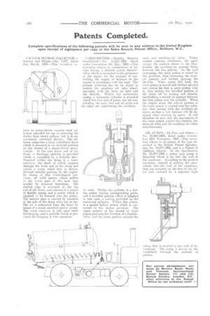
CARBURETTER.—Daimler Motoren tlesellschaft.—N', 10,212/1909, dated under Convention 8th May, 1908.—This invention relates to carburetters of the type having a slidable piston throttlevalve which is connected to the governors of the engine for the purpose of controlling the supply of mixture to the engine in accordance with the load. The present invention has for its object to control the auxiliary air inlet simultaneously with the main air inlet and the throttle. Within the carburetter casing, a stationary cylinder is mounted which has two sets of ports, one set constituting the main fuel and air ports and the other set, constituting the auxiliary air inlet. Within the cylinder is a sliding piston having corresponding ports, and a bevelled portion which is adapted to rest upon a seating provided on the stationary cylinder. Within this piston, is a second hollow piston which is connected to the engine governor. l_Che upper portion of the second or inner piston performs the function of a throttlevalve, and the lower portion controls the main and auxiliary-air inlets. Under normal running conditions, the parts occupy the position shown in the illustration, the auxiliary-air passage being between the two pistons. On the load increasing, the inner piston is raised by the governor, thus increasing the mainair passage and further opening the throUle. When under full load, the inner piston is moved still further upward and carries the first or outer piston with it, thus raising the bevelled portion of the latter off its seating and thereby establishing a second air passage between the first piston and the cylinder. When the engine stops, the conical portion of the inner piston is carried into the cylinder, thus closing both the auxiliary-air inlets, so that a rich mixture will be obtained when starting up again. It will therefore be seen that the movements of the inner piston control the throttle, the main-air inlet and the auxiliary-air inlets simultaneously,
OiL PUMPS.—De Dion and Others.— No. 10,968/1909, dated under Convention_ 20th November, 1908.--This invention relates to oil pumps of the type described in the British Patent Specification N. 10,877/1909, and is a Patent of Addition thereto. In the Specification No. 10,877/1009 a rotary gear pump is described which is let into the wall of the crankcase. According to the present invention, instead of sinking the gearwheels into the wall of the crankcase, they are mounted on the face of the latter and enclosed by a separate light
casing that is secured to the wall of the crankcase. The pump is driven by the i7rankshaft, through the medium of pinions.