


A modern semi-trailer is a sophisticated piece of equipment. A reefer
Page 101
Page 102
Page 103
Page 104
If you've noticed an error in this article please click here to report it so we can fix it.
can nowadays cost as mush as the tractive unit that pulls it, and the trailer is as likely as the tractor to feature anti-lock brakes and airsuspension. Nonetheless, it is still regarded by most operators as the subordinate half of the combination when it comes to servicing. In many cases it only gets attention when a fault crops up.
To find out how to service a modern trailer, we visited Rubery Owen-Rockwell's training school at Llay, near Wrexham. In a previous visit (Workshop October 1989) we learned what the school had to offer — all free of charge. Now we have been back to find out what students learn about how to service a trailer.
Geoff Allman has worked for RO-R for eight years as a customer service engineer sorting out operators' problems; he took us through the servicing procedures.
As with a truck there are three levels of service: A, B and C. Service A should be carried out every four to eight weeks, depending on the operating conditions, and takes about two hours. B is a quarterly chore which takes about four hours. At least once a year a C service is required; on a tri-axle trailer this takes about eight hours.
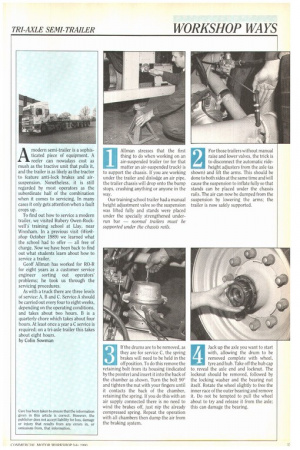
by Cohn Sowman Allman stresses that the first thing to do when working on an air-suspended trailer (or for that matter an air-suspended truck) is to support the chassis. If you are working under the trailer and dislodge an air pipe, the trailer chassis will drop onto the bump stops, crushing anything or anyone in the way.
Our training school trailer had a manual height adjustment valve so the suspension was lifted fully and stands were placed under the specially strengthened underrun bar — normal trailers must be supported under the chassis rails.
For those trailers without manual raise and lower valves, the trick is to disconnect the automatic rideheight adjusters from the axle (as shown) and lift the arms. This should be done to both sides at the same time and Will cause the suspension to inflate fully so that stands can be placed under the chassis rails. The air can now be dumped from the suspension by lowering the arms; the trailer is now safely supported.
2
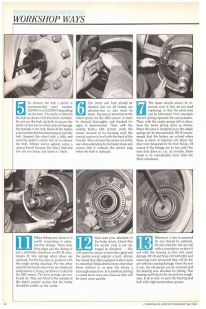
If the drums are to be removed, as they are for service C, the spring brakes will need to be held in the off position. To do this remove the retaining bolt from its housing (indicated by the pointer) and insert it into the back of the chamber as shown. Turn the bolt 900 and tighten the nut with your fingers until it contacts the back of the chamber, retaining the spring. If you do this with an air supply connected there is no need to wind the brakes off, just nip the already compressed spring. Repeat the operation with all chambers then dump the air from the braking system.
3
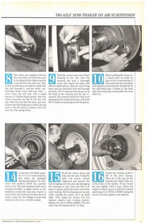
Jack up the axle you want to start with, allowing the drum to be removed complete with wheel, tyre and hub. Take off the hub cap to, reveal the axle end and locknut. The locknut should be removed, followed by the locking washer and the bearing nut itself. Rotate the wheel slightly to free the inner race of the outer bearing and remove it. Do not be tempted to pull the wheel about to try and release it from the axle; this can damage the bearing.
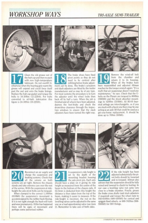
5 To remove the hub a puller is
recommended (part number 21200141 or 21213847 depending
on the axle). The puller is fitted to the hub as shown with the bolts provided. Do not use the hub cap bolts to secure the puller as they are too short and will damage the threads in the hub. Back off the brakes a few notches before attempting to pull the hub. Support the wheel with a dolly and wind the puller's centre bolt in to remove the hub. Allman warns against using a 'greasy board' because the wheel, hub and tyre are too heavy and injury is likely.
The drum and hub should be cleaned, but not all linings are asbestos-free so care must be taken. Pay special attention to the wheel sensor for the ABS system. It must be cleaned thoroughly and checked for signs of deterioration. Then, with the Cirling Wabco ABS system, push the sensor forward in its housing until the conical section is level with the back of the bracket. This will keep the sensor out of the way when attending to the brake shoes and ensure that it contacts the exciter ring when the hub is replaced. The shoes should always be removed, even if they do not need replacing, so that the pivot pins can be lubricated. First uncouple the two springs opposite the cam actuator. Then, with the single spring still in place, lever the lower spring down as shown. When the shoe is hanging loose the single spring can be disconnected. RO-R recommends that the brakes are relined when there is 9mm of material left above the shoe (not measured in the rivet holes). Of course if the linings are to last until the next strip down in, say, six months, there needs to be considerably more than the 9rnm minimum. New shoes are supplied without the cam roller. So if the shoes are to be replaced the rollers must be removed from the old ones. This is done by placing a screwdriver under the clip and levering it, and the roller, out. Exchange shoes come with new clips — never reuse the old ones. Put a small amount of lithium-based grease onto the roller's journals and slip it into the new clip. Offer the clip onto the shoe, put your thumb onto the bridge piece of the clip and push it into the shoe (as shown). You will hear the clip spring home. Push the anchor pins out of their housing on the axle. Give the housing and pins a thorough clean and repack the bush with lithium-based grease. Remove one 0-ring from each pin and push that end through the bush. The 0-ring can then be put on at the back of the housing and the pin recentred. This ensures that the 0-ring is not damaged by the perforated bush, and stops the 0-ring from pushing out all the grease.
10 Before putting the shoes on, a check must be made for
play in the S-cam bearing. If the trailer has been properly and regularly serviced there should not be any detectable play. If there is, the bush may need replacing, and possibly the cross shaft too.
When fitting new shoes it is worth converting to asbestos-free linings. These have blue edges and the change is not a notifiable alteration on RO-R axles. Always fit new springs when shoes are replaced. Put the top shoe in position with the single spring attached. Put the other end into the lower shoe (they are identical) and position it, being careful not to disturb the ABS sensor. The twin springs can now be put on. They are fitted to the outside of the shoes central section but the hooks should be visible on the inside. Next turn your attention to the brake drum. Check that the exciter ring is not da maged or distorted this will cause the sensor to loose the signal and the system would register a fault. Allman has found that ABS-equipped trailers tend to craze their brake drums more often than those without it, so give the drums a thorough inspection. It is pointless putting a crazed drum onto new shoes as they will be worn away quickly,
13 Whenever a hub is removed
its seal should be replaced.
Do not prise the old one out
with a screwdriver or drive it out with the bearing as this will cause damage. RO-R and Snap-On both offer seal removing tools (pictured) that will do the job without causing damage. Once the seal is out, the old grease can be removed and the bearing race checked for pitting. The bearing itself should be checked for roughness. If all is well, re-pack the bearing and hub with high-temperature grease.
A seal has to be fitted squarely if it is to work properly, and many are damaged during installation. To overcome this problem RO-R has another service tool. The seal is placed on the tool's locating shoulder; a spigot locates in the bearing to centre the seal and a mallet is used on the end of the tool to drive the seal home. Listen for the change in note that indicates when it is correctly seated.
14 15 Re-fit the wheel, drum and
hub onto the axle. Using the dolly will ensure correct alignment and prevent the hub dropping onto the axle and damaging the bearings or seal. Once the hub is in place re-grease and fit the inner race of the outer bearing. Put the bearing nut on and, while rotating the wheel, do it up hand tight. Then using the service tool box spanner, adaptor and a torque wrench, tighten the nut to 68Nm (50lbft). The nut must then be backed-off by 2.5 flats.
16 Locate the locking washer's tab in the axle's keyway.
Then see if the peg on the bearing nut aligns with one of the holes in the washer. If not, loosen the nut slightly until it does. When the washer is fitted, secure it with the locknut and torque it to 375Nrn (275Ibft) using the service tool box spanner and adaptor.
17 Clean the old grease out of the hub cap and then re-pack
with new high-temperature lubricant. Do not overfill it, otherwise when the bearing gets warm the grease will expand and could force itself past the seal and onto the brake linings. Replace the hub cap gasket and torque the bolts to 16-30Nm (12-221bft). For hubs converted to oil-bath lubrication this figure is 24-30Nm (18-221bft).
18 The brake shoes have fixed
pivot points so they do not need to be centred after refitting before brake adjustment can be done. The brake's actuators and slack adjusters are fitted by the trailer manufacturer and so may be of any type. For most systems the procedure is to turn the adjuster until the wheel locks then back off by half a turn. When the job is finished and all wheels have been adjusted, depress the foot-brake and check the drum/shoe clearance through the inspection windows to ensure that the slack adjusters have been turned the right way.
19 Remove the wind-off bolt
from the chamber and return it to its housing.
When all the brakes have been reassembled and adjusted Allman reaches for the torque wrench again: -It's a myth that air-suspension doesn't need any maintenance," he says. Check that the Ubolts on the Flexair are torqued to 800Nm (590Ibft) and the shock absorber mountings to 420Nm (310Ibft). All RO-R fourstud airbags are interchangable. so if you are stuck with a burst one there may be one acting as an axle lift that could be used as a get-you-home replacement. It should be done up to 70Nm (50Ibft).
20 Reconnect an air supply and
charge the suspension and braking systems. Check that all the unions on both systems are air tight. Remove the chassis stands and take extreme care over the rest of the service. With the suspension at rideheight the axle pivot bolts can be torqued.
When clamped to the correct 1,100Nm (8101bft) the suspension's movement is accommodated by the rubber bush flexing. If it is not tight enough the bush will turn and wear prematurely. If this has happened there will be signs of movement and perhaps some pulverised rubber.
21 A suspension's ride height is
set by the depth of the mounting bracket housing the axle pivot pin. Each axle should have a plate on it giving its ride height as measured from the centre of the beam to the bottom of the chassis rails. If 63.5mm is deducted from this height the distance is then taken from the top of the beam, making it easier to measure. If the ride-height is incorrect, the rod on the levelling valves can be adjusted in the same way as a load apportioning valve (see item 2). Remember to take care of both sides.
22 If the ride height has been
adjusted substantially the pi vot bolts should be loosened and re-torqued. Allman also advises that the suspension should be fully raised and lowered to check for fouling. In our case a levelling valve rod came very close to a brake chamber. Finally, grease the brake cross shafts (and slack adjusters if required) and torque the wheel nuts to 545-610Nm (400-450Ibft) for conical and spiggot-fixed wheels, or 680-745Nm (500550lbft) for ISO fixings.