 1
1 2
2 3
3 4
4 5
5 6
6 7
7 8
8 9
9 10
10 11
11 12
12 13
13 14
14 15
15 16
16 17
17 18
18 19
19 20
20 21
21 22
22 23
23 24
24 25
25 26
26 27
27 28
28 29
29 30
30 31
31 32
32 33
33 34
34 35
35 36
36 37
37 38
38 39
39 40
40 41
41 42
42 43
43 44
44 45
45 46
46 47
47 48
48 49
49 50
50 51
51 52
52 53
53 54
54 55
55 56
56 57
57 58
58 59
59 60
60 61
61 62
62 63
63 64
64 65
65 66
66 67
67 68
68 69
69 70
70 71
71 72
72 73
73 74
74 75
75 76
76 77
77 78
78 79
79 80
80 81
81 82
82 83
83 84
84 85
85 86
86 87
87 88
88 89
89 90
90 91
91 92
92 93
93 94
94 95
95 96
96 97
97 98
98 99
99 100
100 101
101 102
102 103
103 104
104 105
105 106
106 107
107 108
108 109
109 110
110 111
111 112
112 113
113 114
114 115
115 116
116 117
117 118
118 119
119 120
120 121
121 122
122 123
123 124
124 125
125 126
126 127
127 128
128 129
129 130
130 131
131 132
132 133
133 134
134 135
135 136
136 137
137 138
138 139
139 140
140 141
141 142
142 143
143 144
144 145
145 146
146 147
147 148
148 149
149 150
150 151
151 152
152 153
153 154
154 155
155 156
156 157
157 158
158 159
159 160
160 161
161 162
162 163
163 164
164 165
165 166
166 167
167 168
168 169
169 170
170 171
171 172
172 A NEW , LIGHTWEIGHT DIESEL ENGINE.
Page 78
Page 79
If you've noticed an error in this article please click here to report it so we can fix it.
Burning Heavy Oil, the Held Engine, of Belgian Origin, is Showing Satisfactory Results.
I\ NE of the chief difficulties encountered by designers in adapting the Diesel principle to automobile engines is the high weight factor peculiar to the type. The exceedingly high compression required to produce auto-ignition necessitates a much more substantially built and heavier engine than the automobile type. For this reason the semi-Diesel with moderate compression and hot-wire or hot-bulb ignition is usually employed for industrial vehicle or motor boat work.
In the Held, a new Belgian heavy-oil engine for automobile work, we have • a light motor with medium compression which approaches more closely to the true Diesel than anything of the kind which we have yet seen. The Held is a two-stroke engine in which no heated member of any kind is employed for ignition purposes; it develops its power at a normal speed of 2,000 r.p.m., which is unusually high for a Diesel.
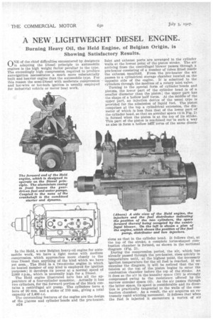
The Held engine illustrated here has all the appearance of a four-cylinder monabloc. Actually it has two cylinders, for the forward portion of the block contains a centrifugal air pump. The cylinders have a bore of 90 mm. and a stoke of 110 mm., giving a total capacity of 1,400 c.c.
The outstanding features of the engine are the design of the ;;;.‘istons and cylinder heads and the pre-heater. D24
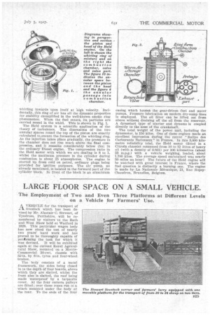
Inlet and exhaust ports are arranged in the cylinder walls at the lowest point of the piston stroke. The air arriving from the centrifugal blower passes through a pre-heater consisting of a number of tubes fitted inside the exhaust manifold. From the pre-heater the air passes to a cylindrical storage chamber located on the opposite side of the engine. It is admitted to the cylinders through the medium of a rotary inlet valve.
Turning to the special form of cylinder heads and pistons, the lower part of the cylinder head is of a smaller diameter than the piston; the upper part has the shape of a hollow half torus. At the middle of the upper part, an injection device of the usual type is provided for the admission of liquid fuel. The piston comprises at the top a cylindrical extension, the diameter of which is less than that of the lower part of the cylinder head, so that an annular space (4 in Fig. 2) is formed when the piston is at the top of its stroke. This part of the piston is machined out in such a way as also tO form a hollow hrif torus of the same dImen sions as that in the cylinder head. It follows that, at the top of the stroke, a complete torus-shaped combustion chamber is formed, as shown in the sectional diagram (Fig. 2).
During the compression period, the air, which has already passed through the pre-heater, rises quickly in temperature until, at the highest point, the necessary ignition temperature for the oil fuel is reached. If we examine the diagram, it will be noticed that the -extension at the top of the piston begins to enter the combustion chamber before the top of the stroke. As it does so the air in the annular space (10) is strongly compressed owing to the resistance offered by the narrow annular space (4). As the air passes through the latter space, its speed is considerable and its direction is practically tangential to the Walls of the combustion chamber. As a result, the air acquires an extremely rapid whirling movement. It follows that when the fuel is injected it encounters a vortex of air whirling inwards upon itself at high velocity. Incidentally, this ring of air has all the dynamic properties for stability exemplified in the well-km:4n smoke ring phenomenon. When the fuel enters, its, particles are carried round in the whirl. This i8 shown in Fig. 1.
The Held system is a scientific application of the theory of turbulence. The dimensions of the two annular spaces round the top of the piston are exactly calculated to, ensure the formation of the whirling ring. As the injection takes place gradually, the pressure in the chamber does not rise much above the final compression, and it remains considerably below that in the ordinary' Diesel engine. The compression ratio in the Held motor with which we are dealing is 8 to 1, whilst the maximum pressure in the cylinder during combustion is about 25 atmospheres. The engine is started up from cold on petrol, ordinary plugs being Provided for ignition purposes. The air pump, as already mentioned, is located in the forward part of the cylinder block. In front of the block is an aluminium casing which houSes the gear-driven fuel and water pumps. Pressure lubrication on modern dry-sump lines is employed. The oil filter can be lifted out from above without draining off the oil from the reservoir. A dynastart type of starter and dynamo is coupled directly to the nose of the crankshaft.
The total weight of the power unit, including the dynamotor, is 150 kilos. One of these engines made an excellent impression during the recent "Rallye des Carburants Nationaux " in France. In this 3,000 kilometre reliability trial, the Held motor (fitted in a Citrokt chassis) consumed from 10 to 12 litres of heavy oil (with a density of 0.861) per 100 kilometres (about 23 m.p.g.) with a vehicle weighing, loaded, about 1,700 kilos. The average speed maintained was nearly 30 miles an hour ! The future of the Held engine will be watched with great interest in France, where the fuel question is distinctly a burning one. The engine is made by La Nationale Mecanique, 21, Rue RopsyChaudron, Bruxelles, Belgium.