 1
1 2
2 3
3 4
4 5
5 6
6 7
7 8
8 9
9 10
10 11
11 12
12 13
13 14
14 15
15 16
16 17
17 18
18 19
19 20
20 21
21 22
22 23
23 24
24 25
25 26
26 27
27 28
28 29
29 30
30 31
31 32
32 33
33 34
34 35
35 36
36 37
37 38
38 39
39 40
40 41
41 42
42 43
43 44
44 45
45 46
46 47
47 48
48 49
49 50
50 51
51 52
52 53
53 54
54 55
55 56
56 57
57 58
58 59
59 60
60 61
61 62
62 63
63 64
64 65
65 66
66 67
67 68
68 69
69 70
70 71
71 72
72 73
73 74
74 75
75 76
76 77
77 78
78 79
79 80
80 81
81 82
82 83
83 84
84 85
85 86
86 87
87 88
88 89
89 90
90 91
91 92
92 93
93 94
94 95
95 96
96 97
97 98
98 99
99 100
100 101
101 102
102 103
103 104
104 105
105 106
106 107
107 108
108 109
109 110
110 111
111 112
112 113
113 114
114 115
115 116
116 117
117 118
118 119
119 120
120 121
121 122
122 123
123 124
124 125
125 126
126 127
127 128
128 129
129 130
130 131
131 132
132 133
133 134
134 135
135 136
136 137
137 138
138 139
139 140
140 141
141 142
142 143
143 144
144 145
145 146
146 147
147 148
148 149
149 150
150 151
151 152
152 153
153 154
154 155
155 156
156 157
157 158
158 159
159 160
160 161
161 162
162 163
163 164
164 165
165 166
166 167
167 168
168 169
169 170
170 171
171 172
172 COOLING THE ENGINE BY STEAM.
Page 110
If you've noticed an error in this article please click here to report it so we can fix it.
A R4surne of Recently Published Patent Specifications.
COOLING by steam is attracting the attention of many .)engineers at the present moment and one of the latest inventions in that direction is of particular interest on account of the source from which it comes. Bentley Motors, Ltd., and "Walter Owen Bentley, in patent No. 271,790, describe an adaptation of the principle which they claim has many advantages over the ordinary method of cooling by water in the radiator. The advantages claimed for this invention are that no matter how severe or prolonged the load imposed upon the engine, and even if the engine be stopped suddenly after severe running, no water will be ejected from the radiator and no local overheating will take place.
The illustration shows the application of the invention to a six-cylindered engine, where it will be seen that, the water level in the engine jackets is just above the tops of the cylinders and that a large steam space is provided abeve the water level in which the formation of steam is permitted. A pipe somewhat resembling a manifold is provided, which is in communication with Six vertical opentopped pipes, which rise to the water level and therefore keep the water at a constant level. Steam that is formed by the boiling of the water passes down these pipes and thence to the lower water level in the, radiator, where it r'ses through the tubee of the latter and, being cooled by the action of the air on the tubes, returns to water form and gravitates to the bottom tank, where it is picked up by the pump and raised to the higher level in the engine jackets.
A vent is provided at the top of the radiator for the escape of excess steam that might otherwise burst the radiator, and a series of baffles is provided to retard its escape. The pump need not be where it is shown, but can preferably be placed so that it is always submerged. With this system a much smaller pump and a smaller quantity of water are needed. Two fillers are provided, one for the lower level and one for the higher level.
A Governor Actuated by Vacuum.
GOVERNING an •engine by means of the varying
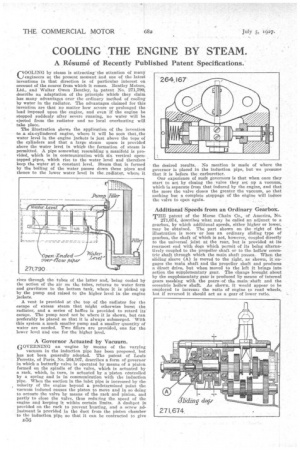
vacuum in the induction pipe has been proposed, but has not been generally adopted. The patent of Louis Ferrette, of Paris; No. 264,167, describes a form of governor in which a butterfly valve is operated by means of a pinion formed on the spindle of the valve, which is actuated by a rack, which, in turn, is actuated by a 'piston centrolled by a spring and is in communication with the induction pipe. When the suction in the inlet pipe is increased by the velocity of the engine beyond a predetermined point the vacuum induced causes the piston to move and in so doing to actuate the valve by means of the rack and pinion, and partly to dose the valve, thus redn:ing the speed of the engine and keeping it within certain limits. A dashpot is provided on the rack to prevent bunting, and a screw adjustment is provided in the duet from the piston chamber to the induction pipe so that it can be contracted to give
05Q the desired results. No mention is made of where the governor is placed in the induction pipe, but we presume that it is before the carburetter.
Our experience of such governors is that when once they start to act by closing the valve they set up a vacuum, which is separate from that induced by the engine, and that the more the valve closes the greater the vacuum, so that nothing but a complete stoppage of the engine will induce the valve to open again.
Additional Speeds from an Ordinary Gearbox.
THE patent of the Morse Chain Co., of America, No. 271,674, describei what may be called an adjunct to a gearbox, by which additional speeds, either higher or lower, may be obtained. The part shown on the right of the illustration is more or less an ordinary sliding type of gearbox, the shaft of which is not, however, coupled directly to the universal joint at the rear, but is provided at its rearmost end with dogs which permit of its being alternatively coupled to the propeller shaft or to the. hollciw eccentric shaft through which the main shaft passes.When the sliding sleeve (A) is moved to the right, as shown, it-engages the main shaft and the propeller shaft and produces a direct drive, but when moved to the left it brings into action the supplementary gear. The change brought about by the supplementary gear is produced hy means of internal gears meshing with the gears, of the main. shaft and the eccentric hollow shaft. As shown, it would appear to be employed to inereas3 the ratio of engine to road wheels, but if reversed it should act as a gear of lower ratio.