


Finishing Ford Brake Drums
Page 60
If you've noticed an error in this article please click here to report it so we can fix it.
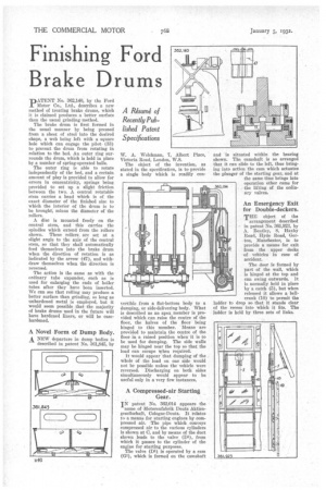
PATENPATENT No. 362,140, by the Ford T Co., Ltd., describes a new method of treating brake drums, which it is claimed produces a better surface than the usual grinding method.
The brake drum is first formed in the usual manner by being pressed from a sheet of steel into the desired shape, a web being left with a square hole which can engage the pilot (33) to prevent the drum from rotating in relation to the bed. An outer ring surrounds the drum, which is held in place by a number of spring-operated balls.
The outer ring is able to rotate independently of the bed, and a certain amount of play is provided to allow for errors in concentricity, springs being provided to set up a slight friction between the two. A central rotatable stein carries a head which is of the exact diameter of the finished size to which the interior of the drum is to he brought, minus the diameter of the rollers.
A disc is mounted freely on the central stem, and this carries the spindles which extend from the rollers shown. These rollers are set at a slight angle to the axis of the central stem, so that they shall automatically feed themselves into the brake drum when the direction of rotation is as indicated by the arrow (47), and withdraw themselves when the direction is reversed.
The action is the same as with the ordinary tube expander, such as is used for enlarging the ends of boiler tubes after they have been inserted. We can see that rolling may produce a better surface than grinding, so long as unhardened metal is employed, but it would seem possible that the majority of brake drums used in the future will have hardened liners, or will be casehardened.
A Novel -Form of Dump Body. A NEW departure in dump bodies is described in patent No. 361,845, by W. A. NVelchman, 7, Albert Place, Victoria Road, London, W.8..
The object of the invention, as stated in the specification, is to provide a single body Which is readily con lertible from a flat-bottom body to a dumping, or side-delivering body. What is described as an apex member is provided which can raise the centre of the floor, the halves of the floor being hinged to this member. Means are provided to maintain the centre of the floor in a raised position when it is to be used for dumping. The side walls may be hinged near the top so that the load can escape ihen required.
It would appear that dumping of the , whole of the load on one side would not be possible unless the vehicle were reversed. Discharging on both sides simultaneously would appear to be useful only in a very few instances.
A Compressed-air Starting Gear.
IN patent No. 362,014 appears the name of Motorenfabrik Dents Aktiengesellschaft, Cologne-Deutz. It relates to a means for starting engines by compressed air. The pipe which conveys compressed air to the various cylinders is shown at 0, and by means of the duct shown leads to the valve (D1), from which it passes to the cylinder of the engine for starting purposes.
The valve (DI) is operated by a cam (G1), which is formed on the camshaft
and is situated within the bearing shown. The camshaft is so arranged that it can slide to the left, thus bringing into action the cam which actuates the ,plunger of the starting gear, and at the same time brings into operation other cams for the lifting of the ordinary valves.
An Emergency Exit for Double-deckers.
THE object of the arrangement described in patent No. 361,923, by A. Bentley, 8, Haxby Road, Hyde Road, Gorton, Manchester, is to provide a means for exit from the upper decks of vehicles in case of accident.
ladder of the ladder The door is formed by part of the wall, which is hinged at the top and can swing outwards. It is normally held in place by a catch (5), but when released it allows a bellcrank (10) to permit the to drop so that it stands clear recess into which it fits. The is held by three sets of links.