


Regenerative Braking
Page 22
If you've noticed an error in this article please click here to report it so we can fix it.
for Battery-electrics
An Attractive Scheme Whereby the Efficiency of the Type Might be Materially Increased
REGENERATIVE braking, whilst common on trolleybuses, is not a feature of .standard battery-electric vehicles, yet it would seem that
• these, with their limited capacity for storing the power upon which they depend for propulsion, would benefit the more from the ability to recover expended energy when decelerating or descending gradients.'
As is welt known, the low range and low speed of . the type form its chief handicap, whilst gains resulting from the use of larger batteries are virtually neutralized by the extra weight inevitably entailed, • Outstanding interest, therefore, attaches to a scheme for applying 'regenerative braking to battery vehicles, for which Mr. J. E. Bowker, of Adelaide, Australia, is responsible and which forms the subject of recently published British patent specification No. 540,265.
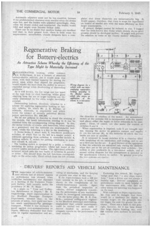
We do not propose to describe in detail the Working of the system, but much information relating tO it can be obtained from the accompanying wiring diagram. In this, the motor (which, of course, also functions, when required, as a generator) and the batteries are unmistakably indicated, whilst the following is a key to the numbering:
• 1, Series fields; 2, shunt field; 3, two-throw double-pole switches, of which that on the left is a. master switch; 4, solenoids operating these switches; 5, controller --Switch; 6, braking switch; 7; switch for putting resistantes in armature circuit; 8, chit-out.
The braking switch is operAted by a pedal, a resistance,. • rendering its action progressive, whilst full travel of the control applies mechanical brakes. The right-hand solenoidactuated switch puts the two banks of batteries in parallel or series. The. second from the left functions correspondingly on the series coils. Third switch from the left reverses
the direction of rotation of. the motor. An unnumbered switch at the extreme left is incorporated with-the master ' and allows .either, the upper or lower solenoids to be energized.. These, • of course, are also under the control of
switches 5 and 6. .
When .regeneration is required, coifs .2_ are brought into use, -causing the Motor to, generate current and .sapply,
• it, via thecut-out (8), to the.batteriei of which the twn banks are now in parallel.
It is proposed to house switches 3 in a chamber filled with insulating • oil for lubrication and cooling; and to act as a blow-out for, the arc. A good feature of the apparatus is that the solenoids are energized only during the nibment when they are in the act of operating their switches. • The svAern is also applicable to a two-motor vehicle, and a second wiring diagram for tho arrangement is included in the specifiCation referred to earlier. In general principles the two systems are similar.