


MAKING BEST USE OF THE FORD.
Page 15
If you've noticed an error in this article please click here to report it so we can fix it.
Valuable Advice on Every Phase of Ford Transport, Which Will Appeal to the Owner, Driver and Repairer.
IN THIS series of hints concerning the Ford light chassis and ton truck wherever they are employed for commercial purposes, we endeavour to deal with the subject from every view-point, so that the advice given will appee 1 to the owner, driver, maintenance engineer, or mechanic. Valuable sources of informs, tion are being tapped for this purpose, and it should be understood that the advice given will be derived from those with an intimate knowledge of the subject.
We shall welcome for inclusion among the hints those which have proved of value to individual lisers, and will make suitable remuneration for any published. What we desire are the results of practice.
165.—Means for Preventing Bad Contacts in Ford Coil Boxes.
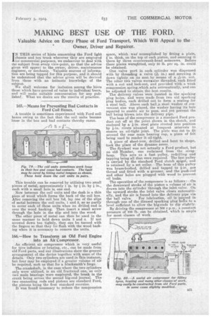
A trouble is sometimes experienced with Ford coil boxes owing to the fact that the coil units become loose in the box and bad contacts thereby ensue.
This trouble can be removed by utilizing two small pieces of metal, approximately 1 in. by in. by in., each with a small hole in one end.
Now between the coil units and the dash is a thin piece of wood which forms the back of the coil box. After removing the coil box lid, lay one of the slips of metal between the coil units, 1 and 2, so as partly to cover each of these units when its drilled end is over the wood backing. Then insert a small screw through the hole in the slip and into the wood.
The other piece of metal can then be used in the same manner to hold down units 3 and 4. If not screwed down too tightly, they can be turned with the fingers so that they lie flush with the wood backing when it is necessary to remove the units.
166.—How to Transform an Old Ford Engine into an Air Compressor.
An efficient air compressor which is very useful for tyre inflation or brazing, etc., can be made from old Ford parts and our illustrations show the general arrangement Of the device together with some of the details. Only two cylinders are used in this instance, but four may be employed if a greater volume of air be required, such as that for a blacksmith's forge.
The crankshaft, in the case where the two cylinders only were utilized, is an old fractured one, as only two main bearings were employed, the break in the crank being across the second big-end journal. The two connecting rods and pistons are standard Ford, the pistons being the first standard oversize.
It was found necessary to reduce the compression
_ space, which was accomplished by fitting a plate, in. thick, on the top of each piston, and securing it there by three countersunk-head setscrews. Before these plates weretfitted, only 50 lb. per sq. in. could be obtained.
One valve port in each cylinder was dispensed with by threading a valve (-e's in.) and screwing it down tightly, on its seat by means of a Ar-iri. nut. The other two valves weretadso threaded, each fitted with a nut and lock-nut, and provided with a weak compression spring.which_acts automatically, and can be adjusted to obtain the best results.
The delivery valves were located in the sparking plug holes, and were made from two old sparking plug bodies, each drilled out to form a seating for a steel ball. Above each ball ..11, steel washer of convenient size was placed, the washer having its hole squared to enable air to pass, and yet prevent the ball being blown into the delivery pipe.
The base of the compressor is a standard Ford product put off at the point shown in the. sketch, and enclosed by a *-in. steel plate riveted into position by *-in. rivets situated at frequent intervals to ensure an oil-tight joint. The plate was cut to fit around the rear main bearing cap, a piece of felt being used to render it oil-tight.
A piece of sheet-iron, drilled and bent to shape, took the place of the dynamo cover.
The flywheel was not actually a Ford product, but an old Humber, one reclaimed from the scrapheap. This acts as a fast pulley, redrilling and tapping being all that were required. The fast pulley is carried by the standard Ford clutch spigot, and is retained by a set collar. The boss of this pulley was brass-bushed, drilled and tapped to *-in. gas thread and fitted with a, greaser, and the push-rod and other holes are plugged with wood to prevent oil leaks.
The operation of the compressor is as follows :—On the downward stroke of the piston a volume of air is drawn into the cylinder through the inlet valve. Onthe upward stroke the inlet valve closes automatically, and the air is forced into the delivery pipe via the ball valve. For lubrication, oil is peered in through one of the disused sparking plug hofes to a level sufficient to allow the big-ends to dip slightly. By driving the compressor at 300 r.p.m.. a constant pressure of 100 lb. can be obtained, which is ample for most classes of work.