


Patents Completed.
Page 22
If you've noticed an error in this article please click here to report it so we can fix it.
DRIVIN GS HAFT COUPLING—The Pullcar Motor Co., Ltd.—No. 25,914, dated 16th November, 1906.—The shaft (a) transmits rotary motion to the shaft (6) through the medium of a universal coupling. The driving shaft (a) and the driven shaft (19, respectively, have jaws (c, d) engaging the two sides of a loose block (e), the jaws being disposed at right angles to each other. The driving shaft is carried within a stationary hollow axle (f) which is supported at the end near the jaw (e), by roller bearings (n). The hub of the road wheel (o) revolves upon a short hollow stub axle (A). The road wheel (a) of the vehicle swings about the hinge (j) through levers or arms connected with the axle portion, after the manner of the wellknown Ackermann system.
ANTI-ST.TP DEVICE. — Fry. — No. 5,034, dated 1st March, 1907.—A flexible band (a) is secured to, and supported by, two pulleys (b) mounted on suitable bearings, and carried by the frame (x) of the vehicle, fore and aft of the driving wheels (y). The length of the band, and the arrangement of the pulleys, are such that the band touches the ground just in advance of the point of contact of the driving wheels of the vehicle with the ground. That part of the band between the suspending pulleys as carried in a supporting trough to prevent sagging. TJ1 order to ensure the bands trailing on the ground in the correct position with relation to the tires of the driving wheels, guide wheels (d) are provided as shown in the figure in dotted lines.
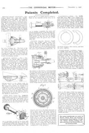
LOCK NUT.—Curd.—No. 13,960/07, dated (under Convention) 13th December, 190L—A locking key is provided with a readily-arranged body (2) which extends through the nut (3) and engages the longitudinal groove (4) of the bolt (5). The nut is provided in each of its faces with a radially-arranged hole (6) to receive the body portion of the key, whereby the nut may be locked at each quarter turn. The groove (4) is of a depth equal to about a third of the diameter of the bolt, so as not to weaken materially the same, and extends longitudinally of the threaded portion of the bolt as shown in the figures. When it is desired to remove the nut, the loon portion of the key may be readily withdrawn from the groove by a suitable tool.
CLUTCH.--Daimler Motoren Gesellschaft.—No. 11,407a, dated, under Convention, 16th May, 1906.—The cone surface (b) is fixed in the flywheel hub (a). The clutch part (c) has an axially-movable cone (d) with spring (1) and limiting bolts (it), and a rigid cylindrical sleeve (di). In the interior of the hollow, cylindrical hub (a), an open brake ring (f), provided with a leather covering (k), is loosely arranged, the ring (f), in consequence of its inward spring action, tending to contract on the cylindrical member (d1) of the clutch part (c). The cylindrical sleeve (dl) carries a brake wedge (1) on its outer surface. The engagement of the clutch pushes this brake wedge between the ends of the brake ring (f), and forces the latter outwards so that it bears against the inner surface of the fly-wheel hub. The brake ring (f) is securely held in the hub (a) by a ring nut (g). Upon engagement of the coupling, the 1 brake wedge (1) presses the ends of the brake ring (f) apart, but a tight engagement of the brake ring with the interior surface of the fly-wheel hub (a) onlytakes place after the cone surface (d) has engaged the cone surface (b), this producing a lesser degree of friction, and effecting compression of the spring (1).
WASHER S.—Parks. — No. 12,798, dated 3rd June, 1907.—This washer consists of two parts, the ends of which have heads and recesses. These are shaped so as to permit the parts of the washer being joined together by striking one of them sufficiently hard to cause the rounded surfaces of the enlarged head,s of one part of the washer, to ride over the curved edges of the heads on the other portion, until the heads engage in the recesses, and lock the parts together.
CRANK-SHAFT L ATH ES.—Potter.— No. 24,904, dated 6th November, 1906.— In order to turn a crank shaft without repeatedly unchucking the same, a lathe is constructed with two stockheads having face plates (E, El), the plate (El) being free to slide on the bed plate. Driving pulleys (A) rotate with the pinion (Al) which gears with a spur wheel (B) ; this spur wheel is geared to, and rotates with, the shaft (C). Two pinions (D, D1) are mounted upon the shaft (C), and these engage with teeth cut on the peripheral faces of the face plates (E, El). The pinions (D, D1) have the same number of teeth as those on the edges of the face plates (E, El), therefore, the face plates (E, El) rotate at the same speed. Fitted to the face plates (E, El) are eccentric plates (F, En) which are adapted to be moved across the face plate by means of a worm (K) gearing with a rack (K1) let into each face plate. Fitted to each of the eccentric plates (E, Fl) is a four-jawed chuck. It will he seen that, by placing the eccentric plates (F, El) which carry the jaw chucks (G and Cl respectively), at the required degree of eccentricity, the crank pin of a crank, or a plurality of crank pins in succession, if at different angles, can be brought to the centre with a minimum of labour and time.