


Braking by Camshaft Timing
Page 80
If you've noticed an error in this article please click here to report it so we can fix it.
TO vary the valve timing, enabling an engine to be used as a compressor and so set up a braking force, is the aim of a device shown in patent No, 767,645 (R. Martin, 9 Rue Jean-L, Forain, Paris XVII).
The camshaft is made in two concentric parts, an outer sleeve carrying the inlet cams (1) and an inner shaft carrying the exhaust cams (2). The outer sleeve is cut away to let these cams protrude.
The outer sleeve is driven by a sprocket (3) but the drive to the inner shaft passes through a helically spline& coupling shown generally at 4. By moving the sleeve axially, an advanceretard setting can be imparted to the exhaust cams. The patent states that if the relative rotation reaches 710, the engine will then act as a compressor on a two-stroke cycle. The compressed air is released at the top of each stroke to avoid having the energy returned.
A MECHANISM TO PREVENT WHEEL-LOCKING
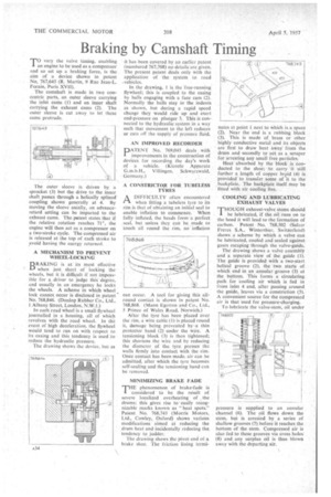
BRAKING is at its most effective when just short of locking the wheels, but it is difficult if not impossible for a . driver to judge this degree, and usually in an emergency he locks the wheels. A scheme in which wheel lock cannot occur is disclosed in patent No. 768,846. (Dunlop Rubber Co., Ltd., 1 Albany Street, London, N.W,I.)
In each road wheel is a small flywheel journalled in a housing, all of which revolves with the road wheel. In the event of high deceleration, the flywheel would tend to run on with respect to its casing and this tendency is used to reduce the hydraulic pressure.
The drawing shows the device, but as
• it has been covered by an earlier patent (numbered 767,708) no details arc given. The present patent deals only with the application of the system to road
In the drawing, 1 is the free-running flywheel; this is coupled to the casing by balls engaging with a face cam (2). Normally the balls stay in the indents as shown, but during a rapid speed change they would ride up and exert end-pressure on plunger 3. This is connected to the hydraulic system in a way such that movement to the left reduces or cuts off the supply of pressure fluid.
AN IMPROVED RECORDER
PATENT No. 769,045 deals with improvements in the construction of devices for recording the day's work of a vehicle. (Kienzle Appa rate G.m.b.H., Villingen, Schwarzwald, Germany.)
• A CONSTRICTOft FOR TUBELESS TYRES
ADIFFICULTY often encountered when fitting a tubeless tyre to its rim is that of obtaining an initial seal to enable inflation to commence. When fully inflated, the beads form a perfect seal, but unless they can be made to touch all round the rim, no inflation
can occur. A tool for giving this allround contact is shown in patent No. 768,868. (Mann Egerton and Co., Ltd., 5 Prince of Wales Road, Norwich.)
After the tyre has been placed over the rim, a wire cable (1) is placed round it, damage being prevented by--a thin protector band (2) under the wire. A tensioning block (3) is then tightened; this shortens the wire and by reducing the diameter of the. tyre presses the walls firmly into contact with the rim. Once contact has been made, air can be admitted, after which the tyre becomes self-sealing and the tensioning band can be removed.
MINIMIZING BRAKE FADE
THE phenomenon of brake-fade is considered to be the result of severe localized overheating of the drums; this gives rise to easily recognizable marks known as "heat spots." Patent No. 768,743 (Morris Motors, Ltd., Cowley, Oxford) shows various modifications aimed at reducing the drum heat and incidentally reducing the, tendency to judder.
The drawing shows the pivot end of a brake shoe. The friction lining termi nates at point 1 next to which is a space (2). Near the end is a rubbing block (3). This is made of brass or other highly conductive metal and its objects are first to draw heat away from the drum and secondly to act as a scraper for arresting any small free particles.
Heat absorbed by the block is conducted to the shoe; to carry it still further a length of copper braid (4) is provided' to transfer some of it to the backplate. The backplate itself may be fitted with air cooling fins.
COOLING AND LUBRICATING EXHAUST VALVES 'THOUGH exhaust-valve stems should 1be lubricated, if the oil runs on to the head it will lead to the formation of carbon. Patent No. 768,502 (Sulzer Freres S.A., Winterthur, Switzerland) shows a scheme by which a valve can be lubricated, cooled and sealed against gases escaping through the valve-guide.
The drawing shows a valve assembly and separate view of the guide (1). The guide is provided with a two-start helical groove (2), the two starts of which end in an annular groove (3) at the bottom. This forms • a circulating path for cooling air which is fed in from inlet 4 and, after passing around the guide, leaves via a constriction (5). A convenient source for the compressed air is that used for pressure-charging.
To lubricate the valve-stem, oil under pressure is supplied to an annular channel (6). The oil flows down the stem, but is arrested by a series of shallow grooves (7) before it reaches the bottom of the stem. Compressed air is also fed to these grooves via cross holes' (8) and any surplus oil is thus blown away with the departing air.