


Interchangeable . Hulibk4k - 0 Asse ublies V EHICLES usually have different types of hub-and-brake
Page 58
If you've noticed an error in this article please click here to report it so we can fix it.
assemblies on front and rear, or on driven and non-driven axles. A scheme for utilizing a standard unit, suitable for any position on the vehicle, forms the subject of patent No. 694,766, from The Timken-Detroit Axle Company, Detroit,
••Michigan, U.S.A. •
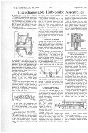
The proposed hub is arranged so that it can be fitted with either end towards the vehicle. The drawing shows the unit as used in a single-wheel driving assembly. In this case the hub (I) has the brake drum secured to the righthand end by screws (2) and the wheel is bolted to flange 3. The tubular axlehousing carries a flange (4) to receive the brake back-plate.
If the unit is required to carry twin wheels, the hub would be turned end. for end, the drum then being held by screws 5, the two wheels being clamped together on the inner flange face (6).
In the case of a front-wheel drive, the wheel is attached as .shown, but the stationary flange (7) then receives a• trunnioned casing which acts as the king-pin of the steering. The centre of the casing is occupied by a universal joint for the axle drive.
In all eases, the dimensions are such that the standard width of track is always maintained. The patent gives drawings of all the assemblies mentioned.
A TIMING-CH.AIN TENTSIONER
• TO maintain the tension in a timing • 1 chain is the aim of a sprocket modification shown in patent No. 694,884 by J. Rix and the Austin Motor Co., Ltd., both of Longbridge Works, Birmingham. The scheme works by inducing
A40 the chain, when on the sprocket, to expand slightly in diameter.
The drawing illustrates one of the several methods described. On each side of the toothed portion of the sprocket is placed a thin split-metal band (1) which rather resembles a piston-ring. This is positioned so that the edges of the chain links rest upon it.
The ring is biased outwards by some variety of spring; in the example shown it takes the form of a wavy steel ribbon (2). In the ease of sprockets having two rows of teeth, the ring can be placed between them.
A COMPACT INJECTOR
clIvIPLIFICATION of the design of hi oil-engine injectors is disclosed in patent No, 695,410, from A. Pischinger, 9 Felix-Dahnplatz, Graz, Austria. The injector has fewer parts than usual and is said to be very economical to manufacture.
In this scheme, the needle-valve is short and is wholly contained in the nozzle end (I). The force from the closing spring is transmitted to the needle by a large-headed pin (2). The pipe connection is an intermediate member which is firmly clamped down by the upper cap-screw (3).
The screwed end (4) projects through a small hole in the side of the body, and assembly has therefore to be performed by inserting• the member from the top. To permit this, its edges are made as portions of a sphere as shown at 5.
A SEMI-INDEPENDENT SUSPENSION SYSTEM
PATENT No. 695,404 shows a suspension system in which the axle moves generally as a whole, but which also permits each wheel to have a limited independent movement. The patentee, B. Alderson, 'Rosemary," Park Avenue, Westward Ho, Devon, states that the scheme effectually prevents rolling on corners.
Referring to the drawing, the wheels are each carried on a swinging arm (1) mounted for rotation in a tubular crossmember (2). The two central spindles meet in the middle, where they are united in a sleeve (3). This carries an upstanding arm which compresses a helical spring (4) when the wheels are lifted. So much forms a complete pension system, but in this case wheels are allowed a slight indepem motion as well.
This is provided in the folios manner; the centre spindles do mot p tively engage sleeve 3, but are provi with vanes which interlock I inwardly projecting vanes in the sle The two sets of vanes are separated rubber blocks to provide resilience, HARDENING CAMSHAFTS DURING CASTING
FROM the Ford Motor Co., I 88 Regent Street, London, comes patent No. 694,277, in vvhicl disclosed some interesting details the production methods employed the manufacture of camshafts. patent refers to castings made by shell-mould process in which pattern is first heated and then cove with a mixture consisting of sand uncured phenolic resin.
• The mixture is then cured and pal into two, thus preldueing a mc :having a high finish. The mouI4 next placed in a steel box and rounded by metal shot to give supp The molten metal is then poured.
The essence of the patent is a met of hardening the working faces of camshaft during the process of coo after casting. To this end, the nic is provided with numerous jets (1) e of which is directed at one of points at which hardening is desire' After the metal has solidified, c pressed air is blown from the jets the resulting chilling effects a harc ing of the work. Air is not the ( coolant that may be used, btl having a more violent queuei action being acceptable.
By carefully interrupting the qug for a controlled time, the residual] Can be allowed to temper the bard parts,