


PATENTS SUMMARIZED.
Page 24
If you've noticed an error in this article please click here to report it so we can fix it.
Another Ricardo Invention.
A difficulty in regard to engines of the Diesel. type is that the compression required for self-ignition of the charge when it is cold, as at starting, is mnah higher than that necessary for ordinary running. Since the compression pressure cannot be readily altered while the engine is running, it follows that the whole structure has to be so designed that it will successfully withstand the highest compression which is needed for starting, as well as that. which may forlow a pre-ignition under this high compression. Mr. Ricardo provides a supplementary chamber which is fitted with a sparking plug. It is provided with an automatic inlet valve, and communicates with the main combustion space by means of a narrow passage. The action is as follows :—
The main inlet valve is timed to open rather late, so that on the suction stroke
the auxiliary valve opens first and admits into the supplementary chamber a small charge of air and gas. So soon as the main valve opens the automatic auxiliary valve cldses and during the remainder of the suctionestroke theopiston induces pure air to the cylinder. The sznall charge of combustible gas within the auxiliary chamber remains practically undisturbed until near the end of the compression stroke, when it is ignited, either by the sparking plug or by the heat of compression. As a .result the pressure in the supplementary chamber rises rapidly and the b,urning gases issue at a high velocity through the narrow entry to the main. combustion head, causing rapid motion of the air in that chamber, and also healing it. The main fuel charge is at this instant allowed to enter through the usual valve, and the whole contents of the cylinder then explode, In certain circumstances it may be desirable to cut nut the ailxiliary chamber and the automatic valve is, in this invention carried in a. seating which is movable in a horizontal direction. The valve 'itself is formed with a face on each side, as shown in the drawing which we reproduce, and when the seating is moved into its innermost position the outer face of the valve closes the aperture between the cylinder and the auliliary chamber. The specification is numbered 108,733, and the address of the patentee is, 13, Dartmouth Street, Westminster, London, S.W.
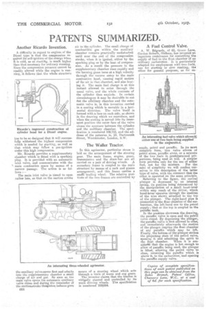
The Waller Tractor.
In this agriraotor, particular stress is laid on the arrangement of the steering gear. The main frame, engine, gears, transmission and the draw-bar are all carried on a pair of driving wheels. A secondary frame is coupled to the main structure by means of a rack and pinion arrangement, and this frame carries a smAll trailing wheel. The relative positions of the two frames are controlled by means of a steering wheel which acts through a train of worm and cog gears.
The inventor claims that the tractor is virtvally steered and controlled by its main driving wheels. The specification is numbered 1081584. A Fuel Control Valve.
A. W. Ecleards, of 65, Green Lane, Garden Suburb, Oldham, has invented an ingenious contrivance for controlling the supply of fuel to the float chamber of an ordinary carburetter. It is ,particularly adapted for employment with two fuels, one for starting or slow running, the other for general purposes, as for ex
An interesting fuel valve which allowsall either one of two fuels being supplied to the car,buretta.
ample, petrol and paraffin. In its most complete form, this valve allows of petrol alone, paraffin alone or a mixture of the two fuels in predetermined
portions, being used at will. A simpler form provides only for the use of either fuel, not for the mixture. For the sake of simplicity we will confine ourselves to the description of the latter type of valve, with the comment that the other is operated on the same principle.
Referring to the figure, the central plunger is depressed by an internal spring, its position being determined by the manipulation of a small hand-lever within easy reach of the driver, which hand-lover operates through the medium of the wire shown attached to the top of the plunger. The right-hand pipe is connected to the float chamber of the carburetter' the left-hand one to the petrol supply; that at the top is coupled to the paraffin tank. In the position show-neon the drawing, the paraffin valve is open and the petrol valve closed. By depressing the plunger, the paraffin valve is first allowed to close, and immediately afterwards the snatiOn of the plunger empties the float chamber of any paraffin which may be left. Finally, the bottom of the plunger strikes the projecting stem Of the petrol valve, opening it and admitting the spirit to the float chamber. When it is eensidernd that the engine is hot enough to allow of paraffin being used; the plunger is lifted, allowing the petrol valve to close, returning the paraffin which is above it, to the carburetter, and opening the paraffin supply valve.