


Novel Pneumatic Suspension System
Page 60
If you've noticed an error in this article please click here to report it so we can fix it.
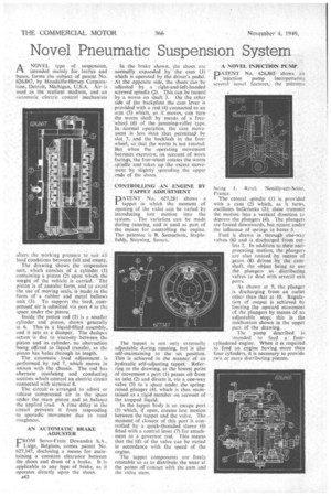
ANOV EL type of suspension, intended mainly for lorries and buses, forms the subject of patent No. 626,867. by Houdaille-Hersey Corporation, Detroit, Michigan, U.S.A. Air-is Used as the resilient medium, and -an ritimatic electric control mechanism alters the working pressure to suit all load conditions between full and empty, . The drawing shows the suspension unit, which consists of a cylinder (1) containing a piston (2) upon which the weight of the vehicle is carried. The piston is of annular form, and to avoid the Use of moving seals, is made in the form of a rubber and metal bellows Unit (3). To support the load, compressed air is admitted via port 4 to the. space under the piston.
Inside the piston rod (5) is a smaller cylinder and piston, shown -.generally at 6. This is a liquid-filled assembly, and it acts as a damper. The dashpot action is due to viscosity 'between the piston and its cylinder, no obstruction being offered to liquid transfer, as the . piston has holes through its length.
The automatic load adjustment . is performed. by rod 7, which moves in unison with the chassis. The rod has.alternate insulating and conducting sectiOns which control an electric circuit connected with terminal 8.
The circuit is arranged to admit or release compressed air in the Space under the main piston And so balance the applied load. A time delay in The circuit prevents it from responding to :sporadicmovement due to road roughness.
AN AUTOMATIC BRAKE ADJUSTER
FROM Servo-Frein Dewandre S.A., Lie.ge, Belgium, comes patent No. 627,347, disclosing a means for maintaining a constant clearance between the shoes and drum of a brake. It is applicable to any type of brake, as it operates directly upon the shoes.
A42
In the brake shown, the shoes are normally expanded by -the. cam (I) which is operated by the driver's pedal. At the opposite side, the shoes Can he adjusted by a right-and-left-handed . screwed spindle (2). This can be turned bya worm on shaft 3. On the oilier side of the backplate the cam lever is provided with a rod (4) connected to an arm (5) which, as it moves, can turn the worm shaft by means of A freewheel. (6) of the jamming-roller type. In normal operation, the cam move incat less than .that permitted by slot.?, and the .backlash in the freewheel, so that the worm is not rotated. But when the operating movement becomes excessive, on account of worn facings, the-free-wheel rotates the worm spindle and takes up the excess movement by slightlY spreading the upper ends of the shoes.
CONTROLLING AN ENGINE BY TAPPET ADJUSTMENT
PATENT No. 627,281 shows a tappet in which the moment of opening of the valve can be varied by introducing last motion into the system. •. The variation can be made during running, and is used as part of the means for controlling the engine. The patentee is 13. Samuelson, Staplefields, Steyning, Sussex.
The tappet is not only externally adjustable during running, but is also self-maintaining to the set position. This is achieved in the manner of an hydraulic self-adjusting tappet. Referring to the drawing, at the lowest point of movement a port (1) passes oilfrom an inlet (2) and directs it, via a one-way valve (3) to a space under the springraised plunger (4), which is thus maintained as a rigid member on account crf the trapped liquid.
In the tappet body is an escape port (5) which, if open, creates lost motion • between the tappet and the valve. The moment of closure of this port is controlled by a quick-threaded sleeve (6) fitted with a control lever (7) for attachment to a governor rod. This means that the lift of the valve can be varied in accordance with the speed of the engine.
The tappet components are freely rotatable so as to distribute the wear at the points of contact with the cam and the valve stem. A NOVEL INJECTION PUMP
PATENT No. 626,865 shows an injectiOn pump incorporating several novel features; the patentcs:
being Retel.
France.
The central spindle—(1) is provided with a cam (2) which, as it turns, oscillates bellcranks (3); these transmit the motion into a vertical direction to depress the plungers (4). The plungers are forced downwards, but return under the influence of springs in bores 5.
Fuel is drawn in through one-way valves (6) and is discharged from out lets 7. In addition to their reciprocating motion, the plungers are also rotated by means of gears (8) driven by the camshaft, the object being to use the plungers as distribution valves to deal with several exit ports.
As shown at 9, the plunger is discharging from an outlet other than .that it 10. Regulation of output is achieved by limiting the upward movement of the plungers by means of an adjustable stop; this is the meehanism shown in the upper part of the drawing.
The pump described is intended to feed a fourcylindered engine. When it is required to :feed an engine having more than four cylinders, it is necessary to provide two or more distributing pistons.