 1
1 2
2 3
3 4
4 5
5 6
6 7
7 8
8 9
9 10
10 11
11 12
12 13
13 14
14 15
15 16
16 17
17 18
18 19
19 20
20 21
21 22
22 23
23 24
24 25
25 26
26 27
27 28
28 29
29 30
30 31
31 32
32 33
33 34
34 35
35 36
36 37
37 38
38 39
39 40
40 41
41 42
42 43
43 44
44 45
45 46
46 47
47 48
48 49
49 50
50 51
51 52
52 53
53 54
54 55
55 56
56 57
57 58
58 59
59 60
60 61
61 62
62 63
63 64
64 65
65 66
66 67
67 68
68 69
69 70
70 71
71 72
72 73
73 74
74 75
75 76
76 77
77 78
78 79
79 80
80 81
81 82
82 83
83 84
84 85
85 86
86 87
87 88
88 89
89 90
90 91
91 92
92 93
93 94
94 95
95 96
96 97
97 98
98 99
99 100
100 101
101 102
102 103
103 104
104 105
105 106
106 107
107 108
108 109
109 110
110 111
111 112
112 113
113 114
114 115
115 116
116 117
117 118
118 119
119 120
120 121
121 122
122 123
123 124
124 125
125 126
126 127
127 128
128 129
129 130
130 131
131 132
132 133
133 134
134 135
135 136
136 137
137 138
138 139
139 140
140 141
141 142
142 143
143 144
144 145
145 146
146 147
147 148
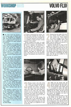
148 Before commencing the service, our fitter first consulted the fault
Page 129
Page 130
Page 131
Page 132
If you've noticed an error in this article please click here to report it so we can fix it.
sheet provided by the driver, knowing that from past experience the driver was fastidious at fisting all items causing problems on the vehicle!
Having completed this check, we could begin with the interior examinations. With the aid of a colleague, the functioning of the exterior lights and indicators is inspected. Follo, ,ng this, the test panel of the electronic driver information system is checked, to see if any malfunctions are indicated. Red lights are used for major items, with yellow ones for less important functions. No problems were shown in our check. Moving from the inside of the cab, the normal exterior checks are then carried out. These include the correct working of the windscreen and headlight wipers and washers, the condition of the wiper blades, and the condition and operation of the heated rear view mirrors.
Operators should also be aware of the problem of water leaks in the FL10 cab. The water is believed to pass into the cab via the drain holes under the screen rubber and the cab A-post. Volvo knows of the problem, and is attempting to stop the water entering by repositioning the drain holes. Our cab was not troubled by any leaks that we could see.
Moving round to the side of the vehicle, our fitter had encountered a recurring problem on the rear parabolic leaf springs. Separating the three leaves are two blocks made from rubber and metal which are screwed to the centre leaf. The rubber tends to wear out, leaving the bare metal protruding and giving the possibility of metal to metal contact. If this is the case, new blocks need to be fitted.
While at the rear of the chassis, the mounting bolts on the fifth-wheel should be checked for tightness. Our fitter finds that the front bolts in particular can work loose, and ought to be tightened at regular intervals. While near the chassis rails, the batteries and the fuel tank mounting are checked. The fuel tank is on the nearside of the vehicle, and is secured by straps. Our fitter has experienced many cases of the straps splitting near the clamp, and this proved to be the case on our truck. The split was not serious, but highlights the need to check the straps regularly.
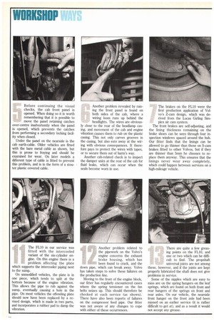
The batteries are housed under a cover on the offside of the chassis rails. The electrolyte levels should be inspected along with the security and condition of the terminal posts. If an operator has fitted any additional wiring, it is best to ensure this has been done in a safe manner. Before continuing the visual checks, the cab front panel is opened. When doing so it is worth remembering that it is possible to move the panel retaining catches over-centre inadvertently when the panel is opened, which prevents the catches from performing a secondary locking facility when closed.
Under the panel on the nearside is the cab earth-cable. Older vehicles are fitted with the bare metal cable as shown, but this is prone to fraying and should be examined for wear. On later models a different type of cable is fitted to prevent this problem, and is in the form of a stouter plastic covered cable. Another problem revealed by raising the front panel is found on both sides of the cab, where a wiring loom runs up behind the headlights. The wires are obvious ly close to the rear of the headlamp casing, and movement of the cab and engine vibration causes them to rub on the plastic casing. This not only carves grooves in the casing, but also eats away at the wiring with obvious consequences. It therefore pays to protect the wires with tapes, or to secure them out of harm's way.
Another cab-related check is to inspect the damper units at the rear of the cab for fluid leaks, which can occur when the seals become worn in use. The brakes on the FL10 were the first production application of Volvo's Z-cam design, which was derived from the Lucas Girling Simplex air cam system.
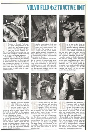
The front brakes are self-adjusting, and the lining thickness remaining on the brake shoes can be seen through four inspection windows spaced around the hub. Our fitter finds that the linings can be allowed to go thinner than those on S-cam brakes fitted to other Volvos, but if they are thinner than 5mm he chooses to replace them anyway. This ensures that the linings never wear away completely, which could happen between services on a high-mileage vehicle. On many of the early FL10 models, there were problems on the front brakes with judder and premature wear. In response to this, Volvo has created a special tool.
The tool works by ensuring that the top shoe is the leading one, which was found to be the best cure for the difficulties.
The tool fits over the wheel studs, and allows the fitter to set both sets of shoes to the same distance from the drum, and to then introduce the necessary bias to the top shoe using a spacer. It should be emphasised that the tool should be used only when fitting new shoes, or when trying to cure a vehicle with the wear/ judder symptoms. Another brake-related check is to look at the brake actuators, because the clamp holding the threaded bar going in to the actuator can slip on the thread, causing braking problems. To check if the clamp is firmly fixed, a lever can be used to exert pressure between the clamp and the actuator (as shown).
The brake pipes under the chassis must also be examined for condition and security. At the same time the load-sensing valve should be checked to see that the mechanism moves freely and is correctly set up. The mechanism is not found to give any particular problems in service so long as it is checked regularly. As on any service, there are the regular chassis checks to be made. Our fitter has found that one area to look out for is the anti-roll bar mounts on the rear axle, where the bolts tend to work loose. It has also been observed that the bushes holding the roll bar wear.
Another location to check is the rear of the front leaf springs, where the bushes on the spring mountings can wear. A lever should be used to check for any unnecessary play. The rubber blocks between the leaves (as described in point 3) should also be inspected. The U-bolts clamping the springs can then be tightened to the specified torque.
The FL10 in our service was fitted with the intercooled variant of the six-cylinder engine. On this engine there is a problem affecting the plate which supports the intercooler piping next to the sump.
On unmodified vehicles, the plate is in one piece, which tends to split at the bottom because of the engine vibration. This allows the pipe to rub against the sump, eventually , causing a hole in the pipe. On most vehicles the offending plate should now have been replaced by a revised design, which is made in two parts, and incorporates a rubber pad to damp the vibration. Another problem related to the pipework on the Volvo's engine concerns the exhaust brake housing, which has been found to crack, and the down pipe, which can break away. Volvo has taken steps to solve these failures on the production line.
Moving to the front of the engine block, our fitter has regularly encountered cases where the spring tensioner on the fan belts seizes up. This should therefore be checked at each service (as shown). There have also been reports of failures on the compressor feed pipe. Our fitter was not aware of any changes to cope with either of these occurrences. There are quite a few greasing points on the FLIO, and one or two which can be difficult to find. The propshaft universal joints are not among these, however, and if the joints are kept properly lubricated the shaft does not give problems in service.
Some of the nipples which are easy to miss are on the spring hangers on the leaf springs, which are found on both front and rear hangers of the springs on front and rear axles. On our vehicle, the nearside front hanger on the front axle had been missed on an earlier service (it is rather difficult to get at), and as a result it would not accept any grease. Another important greasing point which is not at all obvious to those not familiar with the vehicle is on the gearbox release bearing.
Grease is added by using a small cap to be found on the offside of the gearbox, and the cap should be filled with grease before replacing it (as shown).
The kingpins have two greasing points, at the top and the bottom, while there is a further nipple on the brake cross-shafts on all four wheels. Other targets for the grease gun include six more nipples to be found on the fifth-wheel mounting, and others on the cab mechanism including two on the cab pivot points. Having jacked up the front axle, the next task is to look at the kingpins and wheel bearings. Kingpin play can be checked in the time-honoured way of levering the wheel with a bar, while our fitter listened for any excessive movement in the wheel bearings.
The FL10 is fitted with oil-filled hubs, and the oil level should be examined by making a visual check through the transparent window. The correct level is clearly marked by a line. Before moving on to the other wheels, the tyres must be inspected for tread depth and any damage, and the wheel nuts torqued to the required setting. Our vehicle was undergoing a B service, which is typically done every six weeks. In this service, the gearbox and axle oil is not changed, but the levels should be checked. This is done using the normal plugs found on the offside of the gearbox casing (as shown) and the rear of the axle respectively.
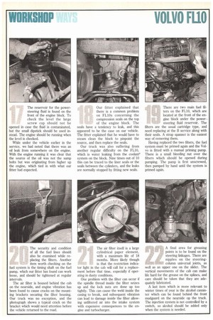
During the B service, the engine oil and filters would usually -be changed, but our FL10 was not normal in that it was fitted with a bypass oil-filter sYstem. With the extra filter, it is only necessary to change the engine oil at a C service (according to the makers of the system), while the bypass filter is changed every service. The reservoir for the powersteering fluid is found on the front of the engine block. To check the level the large screw cap should not be opened in case the fluid is contaminated, but the small dipstick should be used instead. The engine should be running when the level is checked.
While under the vehicle earlier in the service, we had noted that there was an oil leak from somewhere on the engine. With the engine running it was clear that the source of the oil was not the sump bolts but was originating from higher up the engine, which tied in with what our fitter had expected. Our fitter explained that there is a common problem on FL1Os concerning the compression seals on the top of the engine block. The seals have a tendency to leak, and this appeared to be the case on our vehicle. The fitter explained that he would have to steam clean the block to pinpoint the source, and then replace the seals.
Our truck was also suffering from another regular difficulty on the FL10, which is water leaking from the coolant' system on the block. Nine times out of 10 this can be traced to the liner seals or the seals between the cylinders, and the leaks are normally stopped by fitting new seals. There are two main fuel filters on the FL10, which are located at the front of the engine block under the power-. steering fluid reservoir. The filters are the usual cartridge type, and need replacing at the B service along with their seals. A strap spanner is the easiest way of removing them.
Having replaced the two filters, the fuel system must be primed again and the Volvo is fitted with a manual priming pump. There is a small bleeding nut over the filters which should be opened during pumping. The pump is first unscrewed, then pumped by hand until the system is primed again.
The security and condition of all the fuel lines should also be examined while replacing the filters. Another item worth checking on the fuel system is the timing shaft on the fuel pump, which our fitter has found can work loose, and should be tightened at regular intervals.
The air filter is housed behind the cab on the nearside, and engine vibration has been found to cause cracks on the mounting brackets securing the filter housing. Our truck was no exception, and the photograph shows a typical crack on the bracket which would need attention before the vehicle returned to the road. The air filter itself is a large cylindrical paper element, with a maximum life of 18 months. More likely though is that the restriction indica tor light in the cab will call for a replacement before that time, especially if operating in dusty conditions.
One problem with the filter can occur if the spindle thread inside the filter seizes up and the lock nuts are done up too tightly. This can cause the weld inside the casing to break, and subsequent vibration can lead to damage inside the filter allowing unfiltered air into the intake system with expensive consequences to the engine and turbocharger. A final area for greasing points is to be found on the steering linkages. There are nipples on the steeringcolumn universal joints, as well as an upper one on the slider. The vertical movements of the cab can make life hard for the grease on the splines, and care should be taken that they are adequately lubricated.
A last item which is more relevant to winter times of year is the alcohol cannister which can be found behind the front mudguard on the nearside op the truck. The injection system is not controlled by a switch, so alcohol should be added only when the system is needed.