


( From the Drawing pi a l@f o c
Page 52
Page 53
If you've noticed an error in this article please click here to report it so we can fix it.
Automation is the name of the game at Leyland's new engine proving centre as the Engineering Editor explains. . .
KNOCKING LEYLAND has become something of a national sport second only to football in this country. Thus it makes a pleasant change to be able to report on some of the good things which happen to the state-owned company.
As part of a massive E134 million investment programme, Leyland Vehicles opened a new automated engine proving centre at Leyland itself last year. I have recently visited the facility to look at the latest techniques for testing production engines.
The proving centre became fully operational in June of last year. There are 56 test cells arranged in modules with eight beds to each module arranged in four pairs with one operator being responsible for one pair of cells. A further eight beds have still to be commissioned and these will probably be used by the engineering people for endurance testing.
Originally all engines in the 400, 500, 680 and 690 series were catered for Ii both horizontal and vertical form. Now the L12 and TL12 units have been added to the proving centre capability which has a maximum capacity of 750 engines per week.
Having worked in the old engine test at Leyland in the days of my youth I am probably in a better position than most to appreciate the progress that Leyland Motors — sorry, Leyland Vehicles — have made in this direction. In my opinion, one of the most impressive features of the proving centre is the handling equipment.
Engines are heavy lumps to move around with the average weight at around one ton. Leyland has adopted two systems to move the units round, one being a floor level track system involving the use of a carrier trolley and the other a conventional overhead conveyor system.
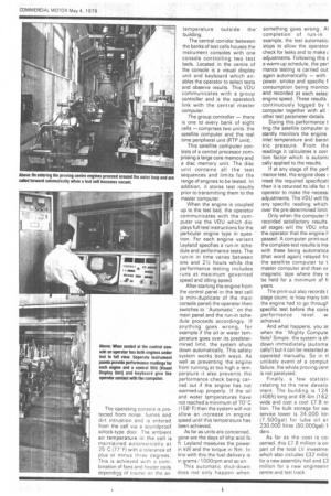
This carrier trolley is an intriguing piece of equipment. It will carry any of the Leyland engines (including industrial units) which comes to an impressive total of 200 variants. To save test-bed time, as much coupling-up as possible is done on the trolley before it ever reaches the bay. This includes rigging up with transducers for measuring inlet depression and connecting up the oil and fuel lines and clutch assembly. In effect when the engine reaches the test bay, it is the complete trolley/engine assembly which is installed rather than just the engine itself. Leyland claims that only 10 minutes are required to have the engine running from the time it enters the cell.
To enable it to be manoeuvred easily the trolley can be made to act as a mini hovercraft by the simple expedient of plugging it in to the factory compressed air system Each trolley has six pads made by the British Hovercraft Corporation fitted underneath which permit easy movement during installation.
The test engines are already fitted with their production "ancillaries at this stage — slave units are not used. After the test cycle is complete and the engine removed, each trolley goes through a hot water /additive pressurised wash before going back to the pre-assembly stage.
Each carrier trolley is equipped with a magnetic destination code pin having 12 code positions. By placing the pin in the appropriate position following each operation, the carrier is directed automatically to the next stage.
On entering the test cell, the carrier is guided — again an automatic process — Into the front docking bar which is mounted on two anti-vibration mounts. The operator then opens out the two rear docking arms and locates them in turn on their own anti-vibration mounts. Disconnecting the air line, allows the "hovercraft" to settle down on to these mounting points where it is automatically locked into position.
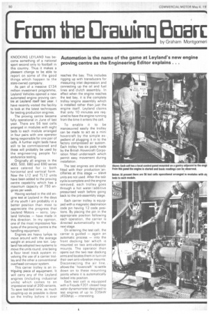
Each test cell is equipped 'with a Froude F201 closed loop water dynamometer designed to test engines of up to 335kVV (450bhp) — interesting. The Operating console is protected from noise, fumes and dirt intrustion and is entered from the cell via a soundproof airlock-type door. The ambient air temperature in the cell is maintained automatically at 25'C (77°F) with a tolerance of plus or minus three degrees. This is achieved with a combination of fans and heater coils depending of course on the air temperature outside the building.
The central corridor between the banks of test cells houses the instrument consoles with one console controlling two test beds. Located in the centre of
the console is .a visual display
unit and keyboard which enables the operator to select tests and observe results. This VDU communicates with a group controller and is the operator's link with the central master computer.
The group controller — there is one to every bank of eight cells — comprises two units: the satellite computer and the real time peripheral unit (RTP unit).
This satellite computer conSists of a central processor comprising a large core memory and a disc memory unit. The disc unit contains all the test sequences and limits for the range of engines to be tested. In addition, it stores test results prior to transmitting them to the master computer.
When the engine is coupled up to the test bed, the operator communicates with the computer via the VDU which displays full test instructions for the particular engine type in question. For each engine variant Leyland specifies a run-in schedule and performance tests. The run-in in time varies between one and 21/2 hours while the performance testing includes runs at maximum governed speed and idling speed.
After starting the engine from the control panel in the test cell (a mini-duplicate of the main console panel) the operator then switches to "Automatic" on the main panel and the run-in schedule proceeds accordingly. If anything goes wrong, for example if the oil or water temperature goes over its predetermined limit, the system shuts down automatically. This safety system works both ways. As well as preventing the engine from running at too high a temperature it also prevents the performance check being carried out if the engine has not warmed-up properly. If the oil and water temperatures have not reached a minimum of 70°C (158°F) then the system will not allow an increase in engine speed until this temperature has been achieved.
As far as units are concerned, gone are the days of bhp and lb ft. Leyland measures the power in kW and the torque in Nm. In line with this the fuel delivery is in grams/ 100Orpm and so on.
This automatic shut-down does not only happen when something goes wrong. Al completion of run-in example, the test automatic; stops to allow the operator check for leaks and to make t adjustments. Following this E a warm-up schedule, the pen
mance testing is carried out again automatically — with power, smoke and specific f consumption being monitoi and recorded at each selec. engine speed. These results continuously logged by computer together with all . other test parameter details.
During this performance t ting the satellite computer ci stantly monitors the engine inlet temperature and baron tric pressure. From thE readings it calculates a corr tion factor which is autorru cally applied to the results.
If at any stage of the pert mance test, the engine does I meet the required specificati then it is returned to idle for I operator to make the necess adjustments. The VDU will flE any specific reading which over the pre-determined limit
Only when the computer 1recorded satisfactory results all stages will the VDU info the operator that the engine lpassed. A computer print-out the complete test results is ma with these being automatica (that word again) relayed frc the satellite computer to t master computer and then or magnetic tape where they v be held for a minimum of fi years.
The print-out also records t stage count; ie how many tim the engine had to go through specific test before the corre performance level w achieved.
And what happens, you w. when the Mighty Compute fails? Simple, the system is sh down immediately (automa cally!) but it can be restarted ar operated manually. So in tl unlikely event of a comput failure, the whole proving cent is not paralysed.
Finally, a few statistii relating to the new develo ment. The building is 124 (406ft) long and 49.4m (162 wide and cost a cool £7.8 m lion. The bulk storage for eac service tower is 34,000 litn (7,500gal) for lube oil ar 230,000 litres (50,000gal) f derv.
As far as the cost is col cerned, this £7.8 million is on part of the total LV investmel which also includes £32 milk for a new assembly hall and £3 million for a new engineerir centre and test track.