


A Self-contained Driving Unit
Page 36
If you've noticed an error in this article please click here to report it so we can fix it.
A Résumé of Patent Specifications That Have Recently Been Published
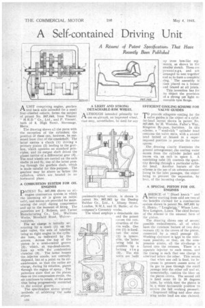
AUNIT comprising engine, gearbox and back axle intended for a small four-wheeled vehicle, forms the subject of patent No. 50,646, from Vincent " H.R.D " Co., Ltd., and P, Vincent, both of 3, High Street, Stevenage, Her t s.
The drawing shows all the parts with the exception of the cylinders; the
position of these can, however, be surmised from that of the crankshaft: The latter carries a crutch (1) driving a primary pinion (2) leading to the gearbox, which operates on standard principles, and its output shaft drives the planet carrier of a differential gear (3).. The road wheels are carried on the axle shafts (4 and 5), one of the latter passing through the gearbox shaft, which is made tubular for this purpose. The gearbox may be above or -below the cylinders, which are located in an horizontal plane.
A COMBUSTION SYSTEM FOR OIL ENGINES
pATENT 567,603 shows au oil-. engine combustion system in which the incoming air is given an initial swirl, and means are provided for maintaining the swirl during compression and up to the moment of firing. The patentees are J. Robson, and -Turner Manufacturing Co., Ltd., Wulfruna Works, Moorlield Road, Wolverhampton. The air charge is initially set, rotating by a mask (1) oil the inlet valve, the axis of rotation being at right angles to the cylinder bore, as indicated by the arrows. Across the top of the piston is a semi-conical groove (2), which, at top-dead-centre, lines up with the combustion chamber (3). The latter houses the. injector nozzle, not centrally disposed, but at a point on its circumference, so that the entire air charge, during its rotation, passes through the region of spray, The patentees state that as the piston rises on the compression stroke, the air continues to rotate, at the same . tine being progressively restricted
to the conical 'groove, .
The specification shows s,everal methods of achieving the s.arne object. A34 A LIGHT AND STRONG DETACHABLE-RIM WHEEL
ALTHOUGII intended primarily for use on aircraft, an improved wheel, that may, nevertheless, be tised for any
pneumatic-tyred vehicle, is shown in patent No. 567,562 by the Dunlop Rubber Co., Ltd., 1, Albany Street,
London, and H. Butler, of the company's Coventry works. • The wheel employs a detachable rim and the patent covers the construction of the rim walls. One rim (1) is fixed,but the other (2) is removable, the latter being held in position by a locking ring (3). The rim units are built
up from box-like segments, as shown •in the smaller sketch. These are pressings, and. are arranged to nest together and so to form a complete ring. The assembly is then placed on it former and brazed at all joints.
This invention has for • its abject the provision of a strong yet light removable tyre flange.
EFFICIENT COOLING SCHEME FOR VALVE GUIDES
TO provide adequate cooling for the valve guides is the object of a cylinder-head layout shown in patent No. 567,660, by H. Weslake, Fuller's Way, Kingston By-pass, Surbiton. In this scheme, a " sandwich " cylinder head contains the valve seats, with a second head bolted or brazed in a superimposed position to provide the water spa ces.
The drawing clearly illustrates the general arrangement; he cooling water enters from the cylinder jacket and leaves via an exit in space 1. A restricting tube (2) controls the quantity flowing through a particular cylinder head. Another feature of the scheme is the use of an asbestos-cement lining to the inlet passages, the object being to prevent the expansion, by heat, of the incoming charge.
A SPECIAL PISTON FOR OIL ENGINES
A BSENCE of "Diesel knock" and better starting from cold are two of the benefits claimed for a combustion system shown in patent No. 567,631 by G. Henry," Loughrigg," Wham Lane, New Longton, Lanes, The chief feature of the stherne is the unusual form of the piston.
Thedrawine shows one of several possible embodiments, • all of which have the common feature of two deep recesses (1) in the crown of the piston. connected , by .a small passage (2). Working clearance is kspt to the minimum possible:so that, on the compression stroke, all the air-charge is forded into the recesses, .There is a separate injector to each recess, and the timing is such that -one charge is admitted before the other.This means:
• that when one cell is fired, its in
• crease in pressure causes some of its gas to pass throngh the small passage into the other cell and so, momentarily-, cushion the blow on the piston crown. The second cell is fired some 10 • fo 20 degrees later, by which time the Piston is in a More favourable position to receive the full working pressure.
-Improved -idling, and-slow .rtine fling under load are 'also claimed.