


Transport Notes for
Page 39
If you've noticed an error in this article please click here to report it so we can fix it.
Those Who Run Bedfords
By' F. S. Groom
Editor, "The Bedford Transport Magazine.
IWITATEVER else you " leave till VV to-morrow," brake adjustment is a job that ought to be done regularly. Most operators are probably familiar with the adjustments on the old Bedfords. Those on the recent models, on which hydraulic brakes are fitted, are, however, considerably different. The following notes explain these adjustments and apply to all such models of 30-cwt. and upwards.
There are twei places where "slack" in the braking system can be taken up—at the brake shoes themselves and at the pedal. which operates them. Adjustment at the shoes automatically takes up any slack on the hand brake, and the hand-brake linkage should not be touched unless new rods or levers have to be fitted, . If the vehicle has been running for some time, start by making sure that the facings themselves do not need replacing. You can de this by lifting up the rubber inspection covers provided for the purpose. On the front wheels you will find them at the most forward point of the back plates; on the rear pair of wheels, they are at the lowest point of the back plates. The facings, as you probably know, should not be allowed to wear below in thickness before they are renewed. When you have satisfied yourself about the facings, set the hamd brake in the " oil " position, scotch the back wheels and jack up the front wheels.
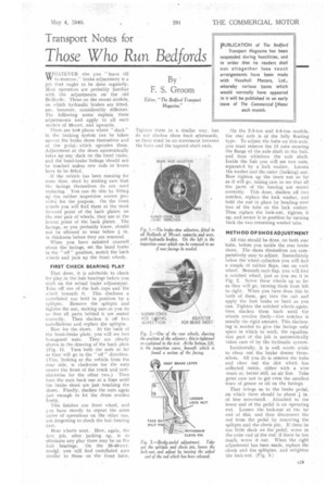
FIRST CHECK BEARING PLAY That done, it is advisable to. check for play in the hub bearings before you start on the actual brake adjustment. Take off one of the hub caps and‘the w heel beneath. it. This discloses a castellated nut held in position by a splitpin. Remove the splitpin and tighten the nut, making sure as you do so that all parts behind it are seated correctly. Then slacken it off two caStellations and replace the splitpin: Now for the shoes. At the back of the front-brake plate, you will see two hexagonal nuts. They are clearly shown in the drawing of the back plate (Fig, 1). Turn both the nuts so far as they will go in the " off " direction. (This, looking at the vehicle from the near side, is clockwise for the nuts nearer the front of the truck and anticlockwise for the other two.) Then turn the nuts back one at a time until the brake shoed are just touching the drum. Finally, slacken the nuts again just enough to let the drum revolve freely.
This finishes one front wheel, and you have merely to repeat the same series of operations on the other one, not forgetting to check the hub bearing first.
Rear wheels next. Here, again, the first job, after . jacking up, is to eliminate any play there may be on the huh bearings. On the 30-40-cut. mo41, you will find castellated nuts similar to those on the front hubs.
Tighten them in a similar way, but do not slacken then2 back afterwards, as there must be no movement between the hubs and the tapered shaft ends. On the 2-3-ton and 9-5-ton models, the rear axle is of the fully floating type. To adjust the hubs on this axle, you must remove the 12 nuts securing the flange of the axle shaft to the huh, and then withdraw the axle shaft. Inside the hub you will see two nuts, separated by a lock washer. Loosen the washer and the outer (locking) nut. Now tighten up the inner nut so far as it will go, taking care to see that all the parts of the bearing are seated correctly. This done, slacken off two notches, replaCe the leek washer, and hold the nut in place by bending over two of the tabs on the lock washer. Then replace. the lock-nut, tighten it up, and secure it in position by turning back the two remaining washer tabs.
METHOD OF SHOE ADJUSTMENT
All this should be done, on both rear hubs, before you tackle the rear brake shoes. The shoes themselves are comparatively easy to adjust. Immediately below the-wheel cylinders you Will find a couple of rubber flaps, one on each wheel. Beneath each flap, you will find a notehed wheel, just as you see it in Fig. 2. Screw these wheels up so far as they will go, turning them from left to right.. When you have done this to both of them, get into the cab and apply the foot brake as hard as you can. Tighten the notched wheels again: then slacken them back until the wheels revolve freely—five notches is usually the right amount. This slackening is needed to give the facings only space in which to work; the equaliza,tion part of the job is automatically taken care of by the hydraulic system.
Incidentally, it is well worth while to clean out the brake drums themselves. All you do is remove the hubs and clear out the dirt which has collected inside, either with a wire arush or, better still, an air line. Take great care not to get even the smallest trace of grease or oil on the facings.
That brings us to the brake pedal, on which there should be about of free. movement. Attached to the lower end of the pedal is an operating rod. Loosen the lock-nut at the far end of this, and then disconnect the rod from the pedal by removing the splitpin and the clevis pin. If these be too little slack on the pedal, screw in the. yoke end of the rod; if there be too much, screw it out. When the right adjustment has been made, replace the clevis and the splitpins, and retighten the lock-nut. (Fig. 3.)