


Developments in Rear-axle DesiFn
Page 62
If you've noticed an error in this article please click here to report it so we can fix it.
IMPROVEMENTS in drop-forged rearaxle-casing design forms the subject of patent No. 407,465, from Kirkstall Forge, Ltd., E. A. AyIwin, and F. R. Cowell, all of Kirkstall Forge, near Leeds. In this type of axle it has hitherto been the practice to carry the crown-wheel and differential assembly in bearings formed inside a domeshaped housing attached to the axle casing by a ring of screws. The inventors claim that this method is, for several reasons, unsatisfactory, weight, noise, and the difficulty of constructing an efficient oil-seal all being instanced.
The suggested improvement calls or the bearing housings to be formed integrally with the main forging. The drawing shows an axle assembly in which the bearings (2) are located in semi-circular recesses (1) bored in the forged body, a bolted-on semi-circular cap (2) completing the honsing.
With this scheme the housings may be bored at the same tool-setting; this gives a degree of concentricity unobtainable with a bolted-up assembly. The cap member (4) may be formed to envelop the mechanism as far as possible, its only duty being that of an oil-seal.
Servo-Clutch Improvements. rROM the well-known maker, Clayton
Dewandre Company, Ltd., Titanic Works, Lincoln, and Jules Fagard, 24 Eastgate, Lincoln, comes patent No. 407,424, describing a device whereby a suction-operated clutch may be allowed to move towards engagement rapidly, vet be retarded as soon as con tact is made between the plates of the clutch.
The illustration shows a vacuum cylinder with its piston (3) connected to a clutch, arm (5). The controlling valve (2) connects the cylinder to either the suction line or the atmosphere. The piston is drawn to the right by the suction, thus withdrawing the clutch. When the suction is destroyed the piston is pulled to the left by the clutch spring, its speed being governed by an air-restricting valve (4).
n48 So far this is standard practice; the novelty in this invention consists of the provision of a spring-loaded pressure-operated valve (1), adjusted so as to open when the piston is moving only the clutch-arm, but to close as soon as the clutch-spring pressure is relieved by the meeting of the plates. This results in a gentle engagement, yet no time is wasted in. bringing the parts together.
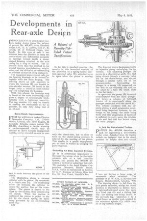
Excluding Air from Injection Systems.
TT is of paramount importance to 'prevent the access of air to the highpressure side of a fuel injection system, and patent No. 407,546 describes a method of achieving this end. The patentee is the Aerol Engine Corporation, Newport, Rhode Island, U.S.A., which is represented in London by A. F. Burgess, of Lloyd, Wise and Co., 10, New Court, Lincoln's Inn. The drawing shows diagrammatically an injection pump embodying the invention. The operating plunger (2) moves in a close-fitting guide (7), fuel being drawn through a one-way valve (3) on the down-stroke, and ejected through a similar valve (1) on the pressure-stroke. Surrounding the plunger is a recess (4) connected on one side to an oil-pump (5) and on the other to a tube (6) which leads to the fuel tank.
In operation, the pump (5) is moved coincidentally with the main plunger, and forces a column of lubricant (castor oil is mentioned) along the passages connected with the recess (4). This column oscillates with the oilpump piston, a small progressive movement being imparted, however, by the design of the pump ; the claim being made that this progression of lubricant is sufficient to carry away the Mixture of air and fuel that has leaked along the main plunger.
A Jack for Two-wheeled Trailers.
PATENT No. 407,626 describes a jack for supporting a two-wheeled trailer when detached from its tractor vehicle, so designed that in its closed position its height does not exceed
2 ins., yet having a large range ot movement when extended. The patentee is N. W. Cox, 2, Ravenscourt Square, Hammersmith, London, W.6.
The drawing shows in full lines the jack partly extended, whilst the closed position is illustrated in dotted lines. A right-and-left-hand. screw has upon it a fixed nut (2) and a sliding nut (3) ; the sliding nut being linked to the movable leg. Operation is by a wheel brace or similar tool, applied to the extension spindle (1), which may be of any suitable length. •