


AN AUTOMATIC VARIABLE SPEED GEAR.
Page 32
If you've noticed an error in this article please click here to report it so we can fix it.
A Resumo of Recently Published Patent Specifications.
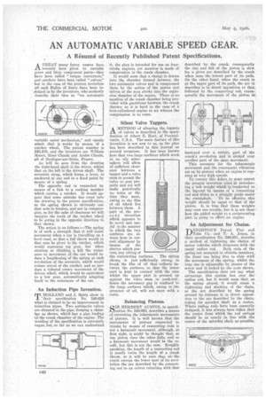
ACHEAT many fancy names have recently been given to variable gears and their component parts—they have been called " torque converters," and ratchets have been called "valves," but in the case of the Present invention ne such flights of fancy have been inAulged in by the inventors, who modestly describe their idea as "*an automatic
variable speed mechanism," and openly admit . that it works by means of a ratchet wheel. The patent number is 245,419, and the inventors are William Manet, Rend Claude and Andre Claude, all of Boulogne-sur-Seine, France. As will be seen from the drawing the right-hand shaft is the driver, whilst that on the left is the driven shaft. The eccentric strap, which forms a lever, is anchored at one end to a fixed point by means of a spring. The opposite end is connected by means of a link to a rocking member which carries a ratchet. It would appear that some mistake has crept into the drawing in the patent specification, as the spring shown is obviously one that acts in tension, and not in compression, so for the sake of clearness we will imagine the teeth of the ratchet wheel to be acting in the opposite direction tb that shown.
The action is as follows :—The spring is of such a strength that it will resist movement when a car is travelling on a level road, so that a full throw would in that case be given to the ratchet, which would represent top gear, but when starting or climbing a hill the resistance to movement of the car would induce a lengthening of the spring at each revolution of the eccentric, which would reduce travel of the ratchet, and so produce a reduced rotary movement of the driven wheel, which would be equivalent to a low gear, automatically adapting itself to the resistance of the car.
An Induction Pipe Invention.
fp HOLLAND and J. Spidy show in 1 'their specification No. 249,626 what is claimed to be an improvement in induction pipes. Two automatic valves are situated in the pipe, forming a chamber as shown, which has a pipe leading ter the crank chamber of the engine. The wording of the specification is extremely vague,, but, so far as we can understand it, the plan is Intended for use on fourstroke engines, yet mention is made of compression in the crank chamber.
It would seem that a charge is drawn into the chamber formed between the two automatic valves and is compressed there by the action of the piston and driven at the next stroke into the explosion chamber of the engine. There is no mention of the crank chamber being provided with partitions between the crank throws, so it is hard in the case of It four-cylindered engine to see whence the compression is to come.
Silent Valve Tappets. '
AMETHOD of silencing tappets
of valves is described in the specification of Albert E. Hutt, of Pennsylvania, U.S.A. The main feature of this invention is not new to us, as the plan has been described in this journal on several occasions. It has been known here that two large surfaces which work in an oily atmo sphere will allow of sufficient clearance between a tappet and a valve stem to permit the valve to seat properly and yet will make practically no noise at the time they meet, owing to the film of oil which lies between them. A part of the present invention which appears to be novel and useful is the manner in which the two surfaces are always kept in correct alignment by means of the sleeves which prevent any tilting of
the contracting surfaces. The spring shown is just sufficiently strong to break the film of oil that 'collects between the surfaces, so that the lower part is kept in contact with the cam whilst the upper part is pressed up against the valve stem or push-rod ; hence the necessary gap is confined to the large surfaces which, owing to the nporesrce of oil, will not meet with a is Balancing Pistons.
SIR HERBERT AUSTIN, in specification No. 249,693, describes a means of correcting the inharmonic movements of pistons. It is well known that the movements of pistons connected to cranks by means of connecting rods is not a harmonic movement, although, at first sight, it might be thought that, as one piston rises the other falls, and so a harmonic movement would be the result, but this is not the case. Roughly speaking, the length of a connecting rod is nearly twice the length of a crank throw, so it will be seen that as the crank sweeps the lower part of its revolution the arc described by the connecting rod to an extent coincides with that
described by the crank, consequently the rise and fall of the piston is slow for a given arc described by the crank when near the lowest part of its path. On the other hand, when the crank is at the upper part of its path, the arc it describes is in direct opposition to that followed by the connecting rod, consequently the movement of the piston is
hastened over a certain part of the crank's revolution and is slowed over another part of the game movement.
This accounts for the inharmonic movement and the consequent vibration set up by pistons when an engine is running at very high speeds. To correct this defect to some extent
the present invention aims introducing a bob weight which is -conneeted to the big-end by means of a connecting rod and slides in a straight guide under
the crankshaft. To be effective this weight should be equal to that of the piston. It is true that these weights may cure one trouble, but it is not clear how the added weight to a reciprocating part is gob* to effect an engine.
An Adjustment for Chains.
DEIGHTON'SPatent Flue and Tube Co. and T.A. Jones, la their specification No, 249,651, describe a method of tightening the chains of motor vehicles which dispenses with the usual radius rod. Both ends of the spring are mounted in slidable members, the front one being free to slide with the movement of the spring, 'whilst the rear one is adjustable by means of the screw and is locked by the nuts shown. The specification does not say what advantage this system has over the radius rod, but it would seem that, as the spring' played, it would cause a tightening and slacking of thechain, as the arc described by the spring around its fulcrum is in direct opposition to the arc described by the chain, taking its sprocket shaft as a centre. Where radius rods have been correctly designed, it has always been taken that the centre from which the rod swings should be as nearly in line with the centre of the sprocket shaft as possible.