


Engines (III).—The Buda.
Page 10

Page 11
Page 12
If you've noticed an error in this article please click here to report it so we can fix it.
• We Now Present Article Three of the Series Dealing with Power Units as Employed on Commercial Vehicles in Use To-day.
The Buda engine is similar in many respects to that one described in the second of this series—the , Continental. Like it, it is American made, but the works are not built on so large a scale, nor is the output anything like so tremendous as the Continental Motor Co., of Michigan.
These enginen are made by the Buda Co., of Harvey, Illinois. They may be said to follow very closely modern ideas of .engine construction as called for by users 1311 this side of the Atlantic, except, per haps, as regards the system of lubrication, whieh follows the American practice of gravity feed and splash, instead of, as is customary in most up-to-date British constructions, that of forced feed to all crankshaft bearings, with splash to gudgeon pins and cylinder wails.
Crankcase.
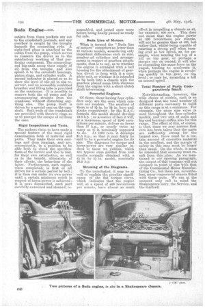
The following description is a general one, and -will cover• any of the types made by this company and likely, to be found in commercial service. For the crankcase, aluminium has been adopted as the material ; this, of course, is on account. of the saving in weight—a serious consideration on a casting of such bulk. Standard practice is followed in its construction, as it is split along the horizontal centre line, the top half being designed so as to carry the crankshaft,it, °IAN being necessary forthe bottom halt to serve-a,s an oil! reservoir. If reference be now made to the sectional illustration of one of these engines, it will be 1seen that C311 this bottom portion of the crankcase is suitably divided by webs and platforms so an to provide independent troughs for each connecting rod, in addition to a sump below, and it is, furthermore, adequately provided with draining and cleaning holes, so that it is not necessary to dismantle the engine whenever it is desired to. remove the old oil and replace it by new.
Crankshaft Cylinders.
The crankshaft is of high-tensile steel, suitably heat-treated, so that under test one square inch of the metal can support a load of 50 tons before breaking. The cylinder castings are fours : it has been found
• more economical and convenient to " use the monobloc design, and in all cases a three-bearing crankshaft is : fitted. It is understood, of course, that we are referring only to four: cylinder engines, and are not concerning ourselves with the six and eight-cylinder machines, several 'examples of which are made by this company, these being, for the purposes of this article, outside our Jurisdiction.
Cooling Arrangements.
Particular care seems to have been paid to the matter of water jacketing of the cylinders and to the arrangement of the water .circulatien generally. The pump delivers cold water from the radiator to a point immediately below the valves ; here, of course, round the exhaust-valve pocket, is where the greatest coaling effect is necessary; thence the water travels round the main body of the cylinders, and out through a large pipe to the radiator Once more. This delivery pipe, it should be noticed, as a general rule forms 'a. part of the large casting which acts as a cover for the top of the cylinder casting. It is designed so as to leave ample water space above the top of the combustion heads, and the opening which it closes is also very useful when it is desired to clean the core holes in the .casting, an operation which, as a rule, immediately precedes thal of machining.
Connecting Rods.
The connecting rods are the usual form, that is to say, a cross section is like the letter II; they are drop forged, of high-tensile steel, and fitted with phosphor-bronze bushes at the upper piston-pin end, and with die-cast ones at the crankshaft end. A very satisfactory job seems to be made of the big-ends in respect of the jointing, as four bolts are provided to each,and the material for these is nickel steel, suitably heat treated. Those of our readers who have had experience of
damaged crankcases, owing to stretching of big-end bolts and con sequent loosening of the bearings, due to inadequacy of these bolts both in respect of number, and also
of material, will readily appreciate -the need for care and attention in the design with regard to this feature.
Valves: Unusual Spring-retaining Arrangement.
The valves, of which the exhaust and induction are interchangeable, are made with nickel-steel heads, electrically welded to mild-steel stems ; the latter are case-hardened as to their extremities, and the complete components are carefully ground to within very fine limits. The arrangement for retaining the valve spring in place, though not new, is sufficiently unusual for us -to have had a special drawing made, in order to illustrate it. Instead of the customary cotter, it will be noticed that the valve stem is turned down for a portion of its length so as to receive a horse-shoeshaped collar ; over this, when in place, the main valve spring collar
drops, enclosing it, so that it is impossible for it to move until the spring is forcibly compressed and the spring collar lifted.
Valve Gear.
In general, the valve gear may be said to be of very sound construction. The valve tappets, beside being of largo diameter, are also of good length and provided with suitable guides. In order that there may bo no trouble owing to excessive escape of lubricant from the crankcase along the tappets, the guides are grooved internally to entrap any oil bending to exude. The bottom end of the tappets are not fitted with rollers, but are palmended, and each is so placed with respect to its cam that on each revolution of the camshaft, the tappet itself is revolved through a small angle ; it thus presents on each occasion a new portion of wearing surface to the cam itself, consequently affording a much larger area for this purpose, and tending considerably to prolong the life of the tappets. All the parts of the valve gear are, of course, carefully hardened and ground.
Provision for Electric Generator if Required.
The arrangement of the timing gears is similar to what might now almost be described as universal practice ; that it to say, they are placed in a compartment in the front end of the crankcase and are accessible by the removal of a large cover. It is notable, however, as showingthe tendency of modern design, that provision is made for a generator for starting and lighting , purposes if this be required.
mug -System Most Important to Owner.
To the owner of a commercial vehicle, perhaps the most useful information which could be provided is that regarding the lubrication of this power unit. With a modern engine" the need for attention is small indeed, and if we except an -occasional grinding-in of valves (and this operation, be it noted, is less frequently reqUired than used to be) then the only care necessary is that of seeing that the engine has a regular and adequate supply of oil, and, further, that this oil is not allowed to remain in the engine case after it-has become stale.
The makers themselves describe the system adopted for oiling this engine as being of the " self-contained positive feed type." The oil is pumped from the oil reservoir, situated, as we have stated, at the bottom of the lower half of the crankcase. A plunger-type pump is used, and. this forces the oil through pipes to small pockets, one above each of the main bearings ; outlets from these pockets are cut to the crankshaft journals, and any overflow is caught by the troughs beneath the connecting rods. A sight-feed glass is attached to the outlet from the pump, which serves to reassure the lriver as to the satisfactory working of that particular component. The connectingrod big-ends scoop their supply of oil from the troughs, and also splash it to the camshaft bearings, piston rings, and cylinder walls. A second indicator is placed so as to show the level of the oil in the reservoir, and an accessible combined breather and filling tube is provided on the crankcase. It is possible to remove both the oil pump and its accompanying strainer from the crankcase without disturbing anything else. The pump itself is driven by a special cam on the camshaft. Both ends of the crankshaft are provided with thrower rings so as to prevqnt the escape of oil from the case.
Rigid Inspections and Tests.
The makers claim to have made a special feature of the most rigid examination both of material and parts. They make their own castings and drop forgings, and are, consequently, in a position to be able both • to check the specifications of the former and also to test, for their own satisfaction, as well as to the benefit, ultimately, of their clients, the behaviour of the latter. Furthermore, each engine, when completed. is first of all driven for a certain period by belt ; it is then run under its .own power until a certain minimum result in respect of horse-power is achieved ; it is next dismantled, each part carefully examined and cleaned, re
assembled, and tested once more before being finally passed as ready for sale.
Buda Line of Motors.
What is termed the " Buda line of motors" comprises no fewer than 18 various models, considering only important differences such as size, number col cylinders and arrange-. ments in respect of gearbox attachments, that is to say, as to whether the engine is arranged with a bell housing for the attachment of gearbox direct to form with it a complete unit, or whether it is intended to be built into a chassis with the gearbox placed some little distance from the engine with a short clutch shaft intervening.
Powerful Engines.
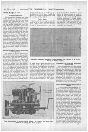
Of these, those having four cylinders only, are the ones which concern our readers. The smallest of them is of 3-1in. by 51, in. bore and stroke respectively ; by the R.A.C. formula this model should develop 19.6 h.p. ; as a matter of fact it will, at a maximum speed of 2100 revolutions per minute, deliver no fewer than 37 h.p., or nearly twice as many as it is nominally supposed to do. At 1000 revs, it develops 21.5 h.p., so that it may fairly be said to be a powerful engine for its size. The diagrams for torque and horse-power are very similar indeed to those we publish, which are typical ones plotted from test results normally obtained with a 41 in. by 51 in. model, nomirially 28.9 h.p.
Meaning of the Diagrams.
To the uninitiated, it may be as well to explain the peculiar significance of the flat torque curve, which indicates that the engine will, at a speed of 400 revolutions per minute, have almost as much
effect in propelling a chassis as at, for example, 800 revs. This does not mean that the engine power at 800 revolutions per minute, will not be greater than at 400, but rather that, whilst being capable of exerting a strong pull when turning over at low speed, as, for example, when nearing the top of a hill on top gear, or perhaps a. steeper one on second, it will also be expending the same force on the wagon, tending to accelerate it„, when perhaps the engine is revolving quickly in top gear, on the level ; or may be, ascending a hill on second speed.
Total Number of Parts Comparatively Small.
Notwithstanding, however, . the wide choice of models, each is SO designed that the total number of different parts ,Beeessary to build up this range is at a minimum. For example, the same size valve is used throughout the four-cylinder models, and two sets of main and big-end bearings suffice also for this range. The effect of this, of course, is that, since we may assume that
• care has been taken that the parts are sufficiently strong for thelargest size, there must be a certain amount of excessive material in the smallest, and the margin of safety in this case must be larger than usual. On the whole, it must be conceded that economy must result from this plan. • As we. mentioned in our opening paragraph, the output of this company will not compare in point of size with that of the Continental Motor Manufacturing Co., but there are nevertheless, many commercial chassis fitted with these units. We can at the moment only call to mind the Shakespeare lorry, the Service, and the Garford.