


A Hold - on Hydraulic Brake A SCHEME for releasing the brakes
Page 76
If you've noticed an error in this article please click here to report it so we can fix it.
1-1 by the normal operation of the clutch pedal is shown in patent No, 706,957, by P. Baldwin and Fiat Societa Per Azioni, Turin, Italy.
The drawing shows a master hydraulic cylinder operating on conventional principles. When the piston (1) is moved to the left, the fluid is forced through the bore in a loose-fitting salable plug (2), through radial holes (3) and under the surrounding rubber ring. This lifts under pressure and acts like a valverubber of a cycle tyre valve. The fluid finally passes into the pipe system from outlet 4.
On the return stroke, the slidable plug retreats slightly to the right and opens a return path past the sealing ring (5). The novel point of the design is the provision of a means for preventing the return movement until desired. To this end, a cam (6) when turned by a lever (7) will hold the sliding plug in the closed position and so hold the brakes on even when the master piston is released.
The lever is coupled to the clutch pedal and the sequence of operations is as follows: Assuming the brakes to be on, the clutch pedal is depressed and the brake pedal released. The brakes remain on until the clutch pedal is allowed to come up, and the driver is thus left with one foot free to work the accelerator.
SUSPENSION SYSTEM FOR ARDUOUS DUTIES
ASUSPENSION system of robust design is shown in patent No. 705,666 (Daimler-Benz A.G., StuttgartUnterttirkheim, Germany).
The drawing shows a front suspension and part of the rear suspension, both of which are made to the same plan. The front axle is triangulated, the apex pointing forwards and secured to the frame by a ball-joint (I). The ball-joint of the rear axle is shown at 2; this is the _point at which the axle pushes the vehicle.
The springs are of the helical variety and are trapped between the axle and a cup (3) on the frame. Sideways
guidance is provided by a single transverse rod ball-jointed to the axle at point 4 and similarly attached to the frame on the opposite side.
Although this causes the axle to move in a slight arc the radius is large enough to be negligible. The term " balljoint" is used in the description, but the joints actually consist of rubber bushes under. compression.
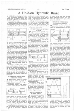
A NEW LOW-VOLTAGE IGNITION SYSTEM
AN ignition system that will work with a maximum voltage of 1,000 instead of the usual 15,000, is shown in patent No. 707,045, by I3endix Aviation Corporation, South Bend, Indiana, U.S.A. Instead of a " jumping" spark it uses one that " creeps" over the surface of a semi-eonducto...
A schematic layout is shown in the -drawing; in this case a magneto is used as the generator, but coil and battery can also be employed. The magneto, shown generally at 1, is of the polarinductor type and can run at any speed irrespective of timing. Its sole function is to generate voltage pulses which are passed through a full-wave rectifier (2) and charge a condenser (3).
This forms a working reservoir from which timed pulses of current can be drawn by a make-and-break mechanism (4). The pulses are then taken to a distributor (5) which directs them to the appropriate plugs.
The sparking plug has across its gap a bridge-piece (6) along which the current tracks and so creates a spark. Suitable materials for the bridge are either a fused mixture of silicon-carbide and iron powder, or a ceramic material impregnated with a conducting powder.
Its resistance should be in the neighbourhood of 10,000 ohms. Another design shows a similar system employing battery and coil, whilst a third scheme is intended for the ignition of gas turbines.
BELLOWS-OPERATED SCREEN WIPER
A SUCTION-OPERATED 1-3 windscreen wiper in which the cylinder and piston are replaced by a rubber bellows, is shown by Joseph Lucas, Ltd., Great King Street, Birmingham, 19, in patent No. 707,083.
The drawing shows that part of the wiper housing in which the bellows (1) is located. The interior is subjected alternately to suction or atmosphere by means of the usual type of snapaction slide-valve as shown at 2. The rest of the unit is covered by an earlier patent No. 683,145.
FLOATING WHEELS FOR AMPHIBIOUS VEHICLES
ALTHOUGH a scheme shown in I-1 patent No. 704,637 is intended mainly for military vehicles of the Jeep
type, it would also be of considerable use in colonial conditions, due to the fact that it enables a vehicle to negotiate snow, deep mud or even travel over water. The patent, which comes from N. Straussler, 5 Clarges Street, Piccadilly, London, W.1, shows an extensible wheel-float which, although normally below the size of the ordinary wheels, can nevertheless be inflated so as to lift the main wheels off the ground.
The drawing shows the normal wheel (1) and the float-wheel alongside it in the operative position. It consists of a rubberized-fabric cylindrical envelope (2) fitted with paddle-like strakes (3) on its periphery. When inflated via valve 4 it assumes the position shown, in which the expansion is limited by steel cables (5 and 6).
In this state, it not only provides a large ground-contact area for snow and mud, but is also buoyant enough to carry the vehicle over water. The wheels still serve to propel the machine because the strakes act as paddles.
When deflated, the whole unit collapses to a diameter below that of the road-wheels. Collapse is assisted by elastic cords (7) and an elastic covering over the steel cables. The latter then lie inside the envelope in a limp condition.