


CONVERTING THE CHEVROLET into a Tractor lorry
Page 51
Page 52
If you've noticed an error in this article please click here to report it so we can fix it.
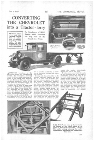
ALTHOUGH introducea to the 13ritish market only comphrativelx recently, the six-cylinder Chevrolet chassis for 80-cwt. loads, which was described in our issues dated Vebruary, 5th and February 12th, has achie.vech considerable popularity. Owing to its stout build, it-is eminently suitable _for conversion to a tractor-lorry.
Bearing this in mind, a design wes prepared by the Harrow Industrial Co., Ltd., Green Lane Works, south Bar row, Middlesex, and we recently in spected the first resulting conversion. When the extension is fitted to he chassis, the pay-load becomes 2i-3 tons, whilst the overall length is 28 ft. A body space of 18 ft. by 3 ft. .9 ins. is a‘ailableland. of course. the body width
can he extended considerably by allowing the bearers to overhang the trailer side-members Dealing with the parts added to the standard Chevrolet chassis, the first step is to place upon the frame sidemembers wooden spacers upon which bed straight channel-steel members. Each of the last-named is attached by four bolts, with lockouts, which pass through the upper web of the Chevrolet frame. To these c-hannels is secured a tubular member placed across the chassis ; this forms the pivot for the turntable frame and is 3 ins. in front of the lateral centre line of the rear axle. Connection to this pivot is made by forked members on the turntable frame 'which dropt over the ends of the tube and are retained in position by quick
release pins passing longitudinally through the ends of the forks.
It is important to note that the length of each rearward arm of the forks is considerably greater than that of its forward complement: thus when the tractor portion is backed on to the stationary trailer—the latter being jacked up to the correct height—the projecting rear arms of the forks make contact with the pivotal bar across the chassfs, thus preventing the tractor portion from moving farther, also providing an automatic-location device. This feature works in conjunction with inclined blocks carrying the tubular member on the vehicle frame; these form ramps to guide the chassis. In this way it is possible quickly to attach the trailer to its tractor. Release is achieved by withdrawing the two pins, jacking up the forward end of the trailer by means of its supporting legs, and the tractor can then move off.
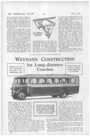
Reverting to the turntable, the fixed portion of this consists of a square channel-steel frame with a patent bearing ring, which forms the spigot for the movable portion, secured to the trailer frame members. Between the main 2bannels there are six cross-members, the two forward ones being gnsseted to provide ample strength around the turntable. It is important to note that no king pin is used in this design.
Semi-elliptic springs are employed, the forward ends being pivoted and the rear extremities shackled. The brakes consist of internal-expanding shoes in 16-in. drums. They .re operated by means of a wire rope which has a hand loop in the centre of the cab floor. The rope passes around a pulley below the cab, then through. an eye fitted over the centre of the turntable and thence to a whipple-tree compensator mounted on a level .with the forward extremities of the springs.. An auxiliary lever projects beyond the frame on the near side and has a ratchet so that the brakes can be made to hold the trailer station ary whenit is supported upon the pair of legs provided under the front of the chassis. Brakes operate on all six wheels of the vehicle.
Considerable interest attaches to these legs, which consist of angle sections bolted to the main frame members ; their lower extremities are joined by brackets through which pass screwed bars, with jack feet and hand wheels at the top. Cross-tics run from the brackets to .the frame members on the opposite sides to provide lateral strength. By the employment of the jacks mentioned, the front end of the trailer, portion can be raised to any desired height, so that connection to the tractor can be made despite any variation in ground level which may exist in areas where the vehicle is likely to operate. There is a clearance of 7 ins, below the jack feet and the ground when the screwed bars are raised to their full height.
Standard Chevrolet wheels and detachable rims are employed ; these carry 32-in. by 6-in, tyres.