


A MECHANICAL STOKER.
Page 40
If you've noticed an error in this article please click here to report it so we can fix it.
A Résumé of Recently Published Paents.
In a recent article, descriptive of a new design of steam Wagon, we referred to the need for the steamer being made to conform with the petrol vehicle, particularly in respect of simplicity arid ease of haisciaing. There can be no doubt that a great asset of the latter type of commercial motor is its aatonsaticity. Once the engine is started, provided petrol. is available in the fuel tank, the driver has practically nothing more to do than drive. He needs to steer his vehicle, control its speed, and, occasionally, to effect changes in the gear ratio by maid, pulation 05 his change speed lever. All this work is necessary also in connection with ,the steam vehicle—the occasions when gear changes are required are perhaps not so frequent—and in addition there are the stolcing and attention to the needs of the steam generator. One useful step towards the diminution of the driver's cares would be the substitutions of automatic mechanical methods of stoking for the present manual means. S. E. Alley has been devoting some attention to this particular phase of steam-Wagon design, and, as appears horn patent specification No. 180,248, has evolved several seemingly simple slut-ions of the problems presented thereby.
The mechanism of a mechanical stoker naturally falls into t•we divisions. There is the actual stoking apparatus, which is in point of fact a conveyor of sorts, and the driving gear for the conveyor. Prime essential features are, as regards the former, that it should be simple and not liable to choke„ and of the latter, that it, should be so operated, from acme part of the chassis machinery for preference, that the fuelsupplied supplied is n proportion to the demand for power it must also be possible to "over-ride" the gear as that, in special circunistances, the driver may supply an additional . quantity,. Of fuel quickly. it will Oiio be appreciated that considerable latitude for adjustment, of the rate of feed is needed.
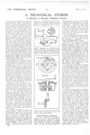
Dealing first wills the stoker itself : three different forms are shown. In one, a spiral conveyor propels the fuel along towards the grate; in another, a reciprocating plunger is employed, and in the third a ram, or blunt-ended poker is used. In all cases the conveyor is located in a passage which is in effect a chute between coal or coke bunker and grate, the said passage being of increasing cross-sectional area throughout so as to eliminate risk of choking. The delivery end of the chute debonches into, and actually forms part of, the boiler fire grate. It is there of rectangular form, as is apparent from one of our illustrations. The rest of the fire-grate is made in sections, which are hinged to the frame of the boiler so that they can readily be swung down and cleared • of ash or clinker.
The driving mechanism is neat, and rather ingenious. Power is derived, in the first place, from some moving part of the vehicle, which can conveniently be made to operate a reciprocating rod. This rod controls a ratchet, which can easily be made more or less effective by masking less or more of its operation. In that manner is adjustment of the rate of feed effected. The ratchet, wheel carries a spider, on the outer end of which is a planetary pinion of an epi
044 cyclic gear. This pinion geari with two wheels, one of which is stationary, being mounted on the casing within which 'the gearing is arranged ; the other is " free wheel " connected to the driven shaftof the mechanism. One of these wheels has one or two teeth more than the other, and the whole effect is a considerable reduction in gear ratio as from the ratchet wheel to the driven shaft. The latter communicates ite motion by any usual means to the actual stoker.
Other Patents of Interest
A peculiar carburetter arrangement, adapted for use in connection with a super-compression engine, is embodied in specification No. 157,359, by Bayerische. Motoren Werke, ,Aktiengesellsehaft. By the use of this device it is claimed that the necessity for a gearbox is eliminated, as the engine can be made to provide increased torque at low speeds of revolution. There are really three carInmetters, complete with jets, choke tubes, and throttle valves, mid the throttles are controlled by a combination of governor and hand control gear. They open successively as the engine speed increases, and close, also succeseively, as it decreases. An arrangement of monobloe engine, in which the induction manifold and passages are cast • in the upper part of the crankcase; is described in No. 163,266, by IVIaybach-Motorenbau.
The lubrication system which is described by J. H. Dickinson, is applicable to any motor vehicle in which the -flywheel habitually runs in oil' it is, however, particularly adaptable for use in connection with the Ford car, and the drawing which accompanies the specification shows it thus applied. A scraper ot " doctor "is applied to the rim and face of the flywheel near the _top,. It collects the eili from the surface and conveys it to a casing formed on the outside of. the gearbox. The oil i5 passed through a filter, then led away through a suitable pipe to a reservoir, whence it can flow again to those portions of the engine which require lubrication. The
specification is No: 179,984_ .
An interesting arrangement of lifting jacks forms the subject of a pat.enteliy G. C. E. 'Hampden, and is described in specification..No. 179,991.The jacks— there may be four of them—are hinged to brackets on the frame, and, normally, are •secured in a horizontal position on the frame. • When releaSed, the foot. of the :jack comes to the ground, and a projecting bracket engages with the under'side Of the axle, .provision being 'made
for, adjustmentof this bracket so that , .
it makes proper. eontact :with the axle. The Jacks may subsequently be pneumatically . or screw operated. If • the fonnere.the cylinder of .t•he •jank ie automatically placed in communication with the source of power as it is lowered to the ground.
friction clatelt is the subject of a patent (No. 180,029) by G. E. Pugh. In certain ways, it resembles, in its construction, a familiar form of universal . joint. At the end of the driving shaft is a hollow sphere, inside which, and at right angles to one another, are twodeep circumferential grooves. Into these grooves enter four pins, each opposed pair of which are connected by a thin annular disc,. These two discs are in contact, and themselves ride in a deep circumferential groove in another disc which is attached to the driven shaft. For free engine, the latter is perpendicular to'its shaft, and the two discs re volve idly in their groove. To engage the clutch, the disc on the driven shaft is moved so that it is no longer at right angles to its shaft. This causes binding to occur between it„ and the two annular discs, and power is accordingly transmitted. The degree of engagement and the power. of the clutch varies with the angularity imposed upon the discs.
E. G. Bell and others describe a simple tipping gear of the rack-andpinion type in No. 180,173.